
7. Safety scenario development (NTB 24-10)
Aims of the chapter:
- To develop safety scenarios that capture uncertainty in the performance of one or more pillars of safety and the fulfilment of their respective safety functions.
- To connect performance assessment, wherein arguments are developed to support the claims of the safety concept, with the radiological consequence analysis that demonstrates the fulfilment of protection criteria.
- To show, specifically, how safety scenarios connect real world phenomena and processes addressed in performance assessment with the highly abstracted models of radiological consequence analyses.
- To describe the safety scenarios, their variants and the calculation cases that are propagated to radiological consequence analysis.
Safety scenarios describe the different possibilities for the initial state and subsequent evolution and performance of key features of the repository system (the pillars of safety). As such, they form an integral part of the treatment of uncertainty in the safety assessment (see Section 4.4). Safety scenarios provide a link between the THM process understanding achieved by modelling of the repository carried out by PA (Chapter 6) and the radionuclide specific transport modelling carried out in the analysis of radiological consequences (Chapter 8; see Tab. 7‑1). The development of safety scenarios is detailed in NTB 24‑21 (Nagra 2024e). Safety scenario development “leads to a systematic focusing of the safety assessment on the important conditions and phenomena relating to performance of the disposal facility” (IAEA 2011b). Each safety scenario consists of a general description of the evolution of the repository system and its environment, starting from its initial state at the time of repository closure, and extending into the future, at least up to the end of the time period for assessment. A safety scenario can have one or more variants. Variants of a given safety scenario share largely the same general description of features, events and processes occurring over time, but may differ, for example, in the extent or timing of key phenomena associated with that safety scenario as well as positioning or properties of a key feature. In addition, each safety scenario or variant will typically have associated with it one or more “calculation cases”. The calculation cases define specific calculations that are carried out to analyse the radiological consequences of a particular safety scenario or variant, including key model abstractions. Care is taken in the selection of the set of safety scenarios to capture uncertainty in the broad evolution of the pillars of safety by bounding and representing the possible ways in which the repository might evolve. The definition of variants captures conceptual uncertainty while parameter uncertainty is treated within the calculation cases (see Section 4.4 and Chapter 8).
Safety scenario development, as part of the general safety assessment workflow, is illustrated in Fig. 7‑1.
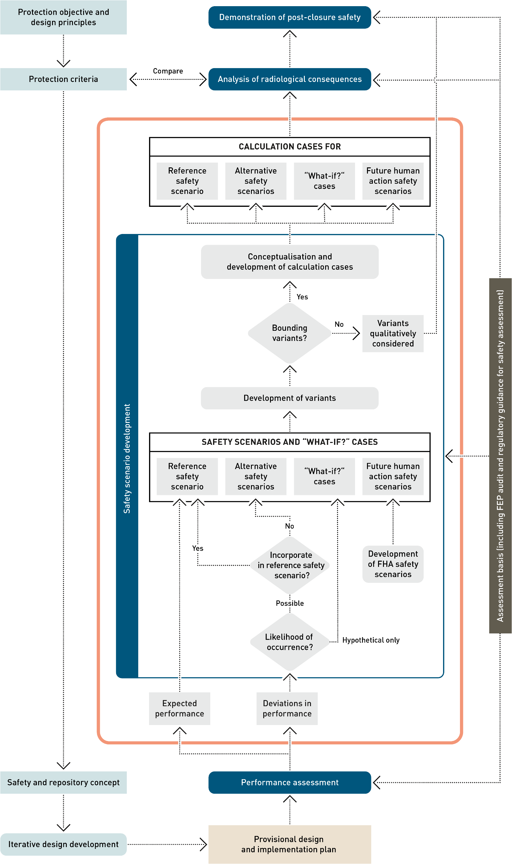
Fig: 7-1Workflow for the post-closure safety case, highlighting, in the orange box, the main elements of the safety scenario development process
Consistent with international and national guidelines, safety scenarios are defined that describe both the expected evolution of the repository and the barriers over the one-million-year time period for assessment, and also less likely and hypothetical evolutions and deviations in performance as identified in the assessment basis and the PA as well as others resulting from future human actions. Specifically, safety scenario development involves the definition of:
- A reference safety scenario
The reference safety scenario is a general description of the expected initial state of the repository barriers, their expected evolution over time, including the release, retention and transport of radionuclides within the repository system, and the assumptions made regarding the biosphere for the analysis of radiological consequences.
- A set of alternative safety scenarios
The alternative safety scenarios include deviations in performance that are judged unlikely, or highly unlikely, but scientifically non-excludable evolutions, on the basis of the assessment and the findings of PA, and lead to a general description of the initial state of the repository barriers and their evolution over time that differs substantially from that of the reference scenario.
- A set of hypothetical “what-if?” cases
Deviations in performance that are judged to be impossible, at least in the one-million-year period for assessment, i.e., which are outside the range of possibilities supported by currently available evidence and knowledge, may nonetheless be propagated to the analysis of radiological consequences as hypothetical “what-if?” cases, designed to demonstrate the robustness of the repository system. As well as “what-if?” cases based on extreme assumptions regarding actual physical phenomena, additional hypothetical “what-if?” cases are also defined that postulate a degraded performance of each of the pillars of safety, unconnected to any physical phenomena. As noted in Section 4.5, they can mitigate possible “completeness uncertainty”, pre-empting possible criticism that some detrimental FEPs are either unknown or have been overlooked.
- A set of safety scenarios considering future human actions (FHAs).
The safety scenarios considering future human action concern the long-term impact of potential actions undertaken by human society on the performance and safety of the repository. They are handled in a broadly similar manner to the alternative safety scenarios but are treated as a separate class of safety scenarios, due to their particularly speculative nature. The main difference in their development compared with the alternative safety scenarios is that, instead of being derived from the assessment basis and deviations in performance identified in the PA, they are derived from FHA FEPs within the FEP database, which are screened to identify those with the potential to perturb the pillars of safety and their safety functions. A full description of Nagra’s methodology for FHAs in the general licence application, its application, and the assessment of the identified FHA safety scenarios can be found in Chapter 2 of NAB 24-09 (Nagra 2024r).
Having defined the safety scenarios, the main elements of uncertainty are identified that, depending on how they are conceptualised within a given safety scenario, could affect the radiological consequences of the scenario. These can include the extent or timing of key phenomena associated with a safety scenario as well as positioning or properties of a key feature. In general, the conceptualisations that are expected to give rise to the highest radiological consequences are taken as the scenario variants that are propagated to the analysis of radiological consequences.
Calculation cases are then defined for each safety scenario variant. This generally requires a degree of geometrical simplification, or abstraction. There may be different ways in which this abstraction can be performed, in which case, especially if the most conservative abstraction cannot be judged in advance of the calculations, more than one calculation case for a given safety scenario variant may be propagated to the analysis of radiological consequences. Additional calculation cases, including probabilistic analyses, are also defined to quantify the effects of parameter uncertainty; see Chapter 8 for details. Several individual calculations may be performed for each calculation case that is propagated to radiological consequence analysis. In particular, different model concepts and models are used for radionuclide transport pathways in the liquid phase on the one hand and two-phase flow and transport of 14C on the other (see Chapter 8 in NAB 24-07 Rev. 1, Nagra 2024w and additional details given in Appendix B of NTB 24-18, Nagra 2024p).
Deviations in performance arising from almost all PA scenarios are incorporated within, or propagated to, one or more safety scenarios and “what-if?” cases, as illustrated in Tab. 7‑1. The difference between safety scenarios and “what-if?” cases on the one hand and PA scenarios on the other is that safety scenarios and “what-if?” cases focus on the properties of the system and their evolution as they affect waste isolation and radionuclide release, retention, transport and radiological consequences. Thus, there is, for example, a “what-if?” case in which a fault is created at some time in the future, and the description given in the present chapter focusses on what this means in terms of radionuclide transport pathways, rather than what could lead to faulting in the first place. The PA scenarios, on the other hand, address events and processes that could potentially degrade the barriers and their safety functions leading to deviations in performance, including phenomena like earthquake, gas pressurisation and thermal stresses that could lead to faulting. Thus, several PA scenarios can be captured by just one (alternative) safety scenario or “what-if?” case, as can be seen in the table. There are also multiple PA scenarios that are captured by the reference safety scenario, through the ranges of parameter values considered in the analysis of this scenario, since the PA scenarios that are captured affect, e.g., the rates of certain processes, but do not fundamentally affect the broad evolution of the pillars of safety. Note that the hypothetical ZEROGAS PA scenario is not directly included in the reference safety scenario parameter ranges. Its impact is, however, considered implicitly through the conservative assumption of fully saturated conditions employed for the modelling of aqueous transport of radionuclides in the analysis of radiological consequences (see Chapter 8 and Appendix A in NTB 24-18, Nagra 2024p).
Further combinations of PA scenarios not captured by the present safety scenarios, or the combination of a PA scenario and an FHA FEP, could, in principle, be conceivable. However, the likelihood of such combinations, though not evaluated quantitatively, is so low that they could, in effect, be considered as “what-if?” cases. Furthermore, the consequences of PA scenarios and FHA FEPs considered individually can, in some instances, be greater if they are considered in combination. For example, the presence of an undetected fault, which is considered as an alternative safety scenario, will lead to reduced gas pressures in the repository, which would lessen the impact of gas-mediated transport of 14C in the event of a borehole later being drilled and penetrating the repository underground structures. In practice, the consequences of such combinations are, in any case, bounded by the extreme “what-if?” cases mentioned above.
The comprehensiveness of the safety scenarios described in this chapter is assessed as part of the wider assessment of the comprehensiveness of the post-closure safety case carried out by means of the FEP audit (see Section 5.5).
Tab. 7‑1:Incorporation of PA scenarios in safety scenarios and “what-if?” cases
Colouring indicates whether a PA scenario is incorporated in the reference safety scenario, an alternative safety scenario, or a “what-if?” case.
|
Performance assessment scenarios |
Safety scenarios |
“What-if?” cases
|
||||||
|
Reference safety scenario |
Alternative safety scenarios |
Related to physical phenomena |
Hypothetical degraded performance of pillar of safety |
|||||
|
Hydraulically active confining geological unit |
Undetected fault |
Undetected fault with hypothetically high transmissivity |
Future creation or reactivation of a fault |
Repository excavation |
||||
|
EXPERF |
Expected performance |
RS |
||||||
|
MKALK |
Exfiltration to Muschelkalk |
RS-KEUPER_ INACTIVE |
||||||
|
UPFLOW |
Upflow with artesian pressure in Keuper |
|
||||||
|
DWNFLW |
Downflow with artesian pressure in Malm |
|
||||||
|
HETOPA |
Heterogeneous Opalinus Clay |
|
||||||
|
PESSGAS |
Pessimistic gas generation rate (L/ILW) |
|
||||||
|
UBGAS |
Upper bound gas source term (HLW) |
|
||||||
|
V3PERM |
Highly permeable V3 seals |
|
WI-V3 |
|||||
|
HARDBED |
Hard beds as release paths |
AS-HA |
||||||
|
HERWIS |
«Herrenwis Unit» as release path |
AS-HA/CD |
||||||
|
FLTHLWP |
Undetected fault parallel to HLW drifts |
AS-FLT-HLW-Along |
WI-FLT-HLW-Along |
|||||
|
FLTHLWN |
Undetected fault normal to HLW drifts |
AS-FLT-HLW-Across |
WI-FLT-HLW-Across |
|||||
|
FLTLILW |
Undetected fault affecting L/ILW caverns |
AS-FLT-L/ILW |
WI-FLT-L/ILW |
|||||
|
UBHEAT |
See RIEHLW |
WI-FLT/RA-HLW |
||||||
|
RIEHLW |
Thermally- and gas-induced faulting (HLW) |
WI-FLT/RA-HLW |
||||||
|
RIELILW |
Gas-induced faulting (L/ILW) |
WI-FLT/RA-L/ILW |
||||||
|
SEISHLW |
Earthquake affecting HLW drifts |
WI-FLT/RA-HLW |
||||||
|
SEISLILW |
Earthquake affecting L/ILW caverns |
WI-FLT/RA-L/ILW |
||||||
|
LOSSFLT |
Fault activation due to overburden loss |
WI-FLT/RA |
||||||
|
LOSSOB |
Permeability increase due to overburden loss |
not explicitly represented |
||||||
|
IRMAX |
Instant release of entire I-129 activity |
WI-SF-IRF |
||||||
|
WPFAIL |
Canister failure at time of repository closure |
WI-HLW-CAN |
||||||
|
ZEROGAS |
No gas generation |
not addressed |
||||||
In the reference safety scenario, the engineered barriers are assumed to be implemented according to the provisional repository design, as described in Section 3.3. The geological barrier (i.e., the CRZ) has the characteristics inferred from site characterisation and understanding, as described in Section 5.2. The engineered and geological barriers are further assumed to evolve and perform according to the phenomenological description of their expected evolution given in NAB 24-20 Rev. 1 (Nagra 2024m) and summarised in the present report in Section 5.3. This phenomenological description is supported by the results of the performance assessment as described in NTB 24‑22 Rev. 1 (Nagra 2024u) and is also in accordance with the current safety and repository concept presented in Chapter 3 of NAB 24‑18 Rev. 1 (Nagra 2024s) and summarised in the present report in Section 3.2. Human intrusion and other future human actions, either deliberate or inadvertent, that could impair the functionality of the repository are assumed not to occur during the post-closure period in the reference safety scenario. This is justified by the placement of the repository in a deep underground location where human intrusion is unlikely and which is isolated from human actions occurring at or near the surface. Criticality safety in the post-closure phase is assumed, since it will be a design requirement of the repository, specifically, for the HLW final disposal canister and for the HLW canister loading plans. Criticality safety will be ensured through the implementation of technical and administrative measures (NAB 24-03, Nagra 2024j).
Based on the performance assessment, repository-induced effects associated with heat, gas and dissolved chemical species are expected to have minimal effects on the geological environment. Repository-generated heat could, however, lead to a narrow zone of altered bentonite around the HLW canisters, which is considered in the modelling carried out in the analysis of radiological consequences (see Appendix B, Fig. B-1, of NTB 24‑18, Nagra 2024p). Stress changes during the construction of the underground openings will result in the formation of Excavation Damaged Zones (EDZs) which will largely re-seal over time. However, their constant presence is conservatively accounted for in the modelling carried out in the analysis of radiological consequences. Repository-generated gas will permeate much of the closure system but will be largely retained underground by the V3 seals and slowly, over a period of tens of thousands of years or more, dissolve and diffuse into the host rock.
There will also be some changes associated with long-term climatic and geological processes. The repository is planned to be constructed deep underground, in a location where it is not susceptible to geological events and processes of relevance to post-closure safety. The future formation of permafrost and glaciers above the repository would affect hydraulic gradients, but the resulting variability in the gradients falls within the range of uncertainty covered by parameter variations in the analysis of the radiological consequences of this scenario. In addition, long-term glacial and fluviatile erosion processes acting at the surface will gradually reduce the thickness of the overburden above the repository. Studies of the future erosion processes indicate that, considering the 5 – 95% probability range, between ~ 350 and 670 m of overburden are expected to remain above the repository (see, e.g., Section 6.4.4 of the Geosynthesis of Northern Switzerland, NTB 24‑17, Nagra 2024i). It is also shown in Section 5.7.4 of NTB 24-17 (Nagra 2024i) that the minimum overburden of 200 m is sufficient for the Opalinus clay to maintain its self-sealing capacity. There may be some impact of the loss of overburden on the hydraulic conductivity of the Opalinus clay, but this again falls within the range of uncertainty covered by parameter variations in the analysis of the radiological consequences of this safety scenario. The impact of extreme erosion which leads to an excavation of the repository is discussed in the separate report NAB 24-08 Rev. 1 (Nagra 2024q).
The release of radionuclides from the repository during its expected evolution in the reference safety scenario and their retention and transport in the repository barriers are described phenomenologically in Section 5.4. Radionuclides will be retained within the HLW canisters until the canisters eventually become breached (see Section 6.1.), and most will be released only slowly thereafter, as the waste packages degrade. Radionuclides will be released more rapidly from the waste packages and containers for L/ILW.
Radionuclides that are dissolved in water migrate away from the waste packages predominantly by diffusion and, upon reaching one of the deep aquifers, by advection. Given the geometry of the CRZ with large horizontal distances from the repository to potential exfiltration pathways, this transport can be approximated by 1D vertical transport (see Section 8.1 for more details on the implementation). Radionuclides that form volatile species, principally 14C as methane, mix with, and are transported by, repository-generated gases through the engineered barriers and could also enter the CRZ. In contrast to the aqueous phase transport, the 3D characteristics of gas transport must be considered (see Section 8.1 for more details on the implementation). These radionuclides also eventually dissolve in porewater within the repository barrier system or within the deep aquifers. Radionuclides that do not decay in transit could eventually reach the biosphere.
Biosphere dose conversion factors (BDCFs) are calculated to convert the radionuclide release rate to dose rates by assuming different enveloping biospheres with respect to climate and geomorphology. Different biospheres are considered via calculation cases as described below in Section 7.2.3. Since it is not possible to make a statement about when which biosphere will occur in the far future, all of the different biospheres are evaluated for the whole time period for assessment (i.e., assuming constant climatic conditions) within the reference safety scenario.
The starting point for the conceptualisation of the CRZ is the geological knowledge as described in Section 5.2.1, which is abstracted as illustrated below in Fig. 7‑2 and Tab. 7‑2. The CRZ, in the reference conceptualisation, is taken to extend between the upper deep aquifer above the repository (the Malm aquifer) and down below the repository to the Keuper aquifer. The geosphere modelling domain in the analysis of radiological consequences is also bounded, at the top, by the Malm aquifer, but extends below the Keuper aquifer to the deeper Muschelkalk aquifer.
Within the confining geological units of the Opalinus Clay, there are a number of thin competent (i.e., hard and brittle) horizonal rock units, including the hard beds, embedded between layers of more plastic clay. In the reference safety scenario, in line with current understanding of the site, these rock units are taken to be sparsely fractured and not to form horizontally connected pathways for radionuclide transport (the presence of a hydraulically active confining unit is considered as an alternative safety scenario; see Section 7.3.1).
Local conductive layers within the Keuper aquifer below the repository have been identified towards the area where the L/ILW repository section is planned; however, such features have not been observed in the area where the HLW repository section is planned. Furthermore, groundwater within the Keuper aquifer is characterised by very long residence times and it could be possible that the aquifer is hydrogeologically inactive (Section 4.5.5.4 in NTB 24-17, Nagra 2024i), at least below the HLW repository section. Thus, two conceptualisations are considered (see Fig. 7‑3):
-
Reference conceptualisation: it is conservatively assumed that the Keuper aquifer is hydraulically active and forms a significant advective transport path below the repository.
-
Variant: the Keuper aquifer below the HLW repository section is inactive and radionuclides are only transported vertically across it by diffusion; the CRZ extends vertically downwards to the Muschelkalk aquifer.
Radionuclides reaching the hydraulically active Keuper aquifer can either be transported vertically across it, predominantly by diffusion, or be diverted into the aquifer and conveyed by groundwater flow to a regional aquifer (considered part of the biosphere), where they become substantially diluted. Radionuclides that reach the other deep aquifers, at the boundaries of the geosphere model, are also conveyed to, and diluted in, the biosphere. Any 14C reaching the deep aquifers in the form of gaseous methane is assumed to dissolve. The significant transport time for dissolved radionuclides within these aquifers as well as between these beds and the biosphere is conservatively neglected. i.e., radionuclides that are diverted into deep aquifers are assumed to be directly and instantaneously transferred to the regional aquifer in the biosphere.
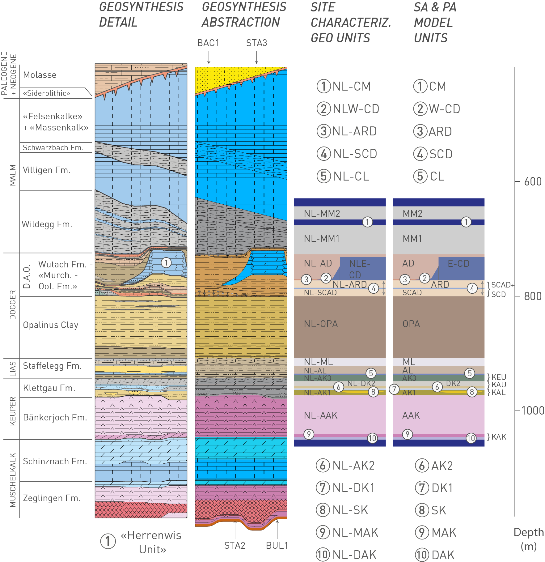
Fig. 7‑2:Abstraction of the sedimentary Mesozoic sequence at the site into units of comparable transport parameters
The abstraction results in the generation of the local “layer-cake” model units for performance assessment and for the analysis of radiological consequences (“SA & PA model units”). D.A.O.: Dogger Group above Opalinus Clay.
Tab. 7‑2:Stratigraphic units, geological abstracted units and abstracted model units for performance assessment and for the analysis of radiological consequences
|
Stratigraphic unit |
Abstracted unit and full name |
Abstracted model unit |
|
|
Wildegg Fm. |
MM2 |
Marly Malm |
MM2 |
|
CM |
Calcareous Malm |
CM |
|
|
MM1 |
Marly Malm |
MM1 |
|
|
Dogger Group above Opalinus Clay |
AD |
Argillaceous Dogger |
AD |
|
E-CD / W-CD |
Calcareous Dogger («Herrenwis Unit») |
E-CD / W-CD |
|
|
SCD |
Sandy-Calcareous Dogger |
SCAD+SCD |
|
|
SCAD |
Sandy-Calcareous-Argillaceous Dogger |
||
|
Opalinus Clay |
OPA |
Opalinus Clay |
OPA |
|
Staffelegg Fm. |
ML |
Marly Lias |
ML |
|
AL |
Argillaceous Lias |
AL |
|
|
CL |
Calcareous Lias |
KEU |
|
|
Klettgau Fm. |
AK3 |
Argillaceous Keuper |
|
|
DK2 |
Dolomitic Keuper |
KAU |
|
|
AK2 |
Argillaceous Keuper |
||
|
DK1 |
Dolomitic Keuper |
KAL |
|
|
AK1/SK |
Argillaceous Keuper / Sandy Keuper |
||
|
Bänkerjoch Fm. |
AAK |
Anhydritic-Argillaceous Keuper |
AAK |
|
MAK |
Massive Anhydritic Keuper |
KAK |
|
|
DAK |
Dolomitic-Anhydritic Keuper |
||
The calculation cases for the reference and variant conceptualisations of the reference safety scenario are shown schematically in Fig. 7‑3. The calculation cases are propagated to radiological consequence analysis and are furthermore summarised in tables in Chapter 8, where the calculation results are presented and discussed.
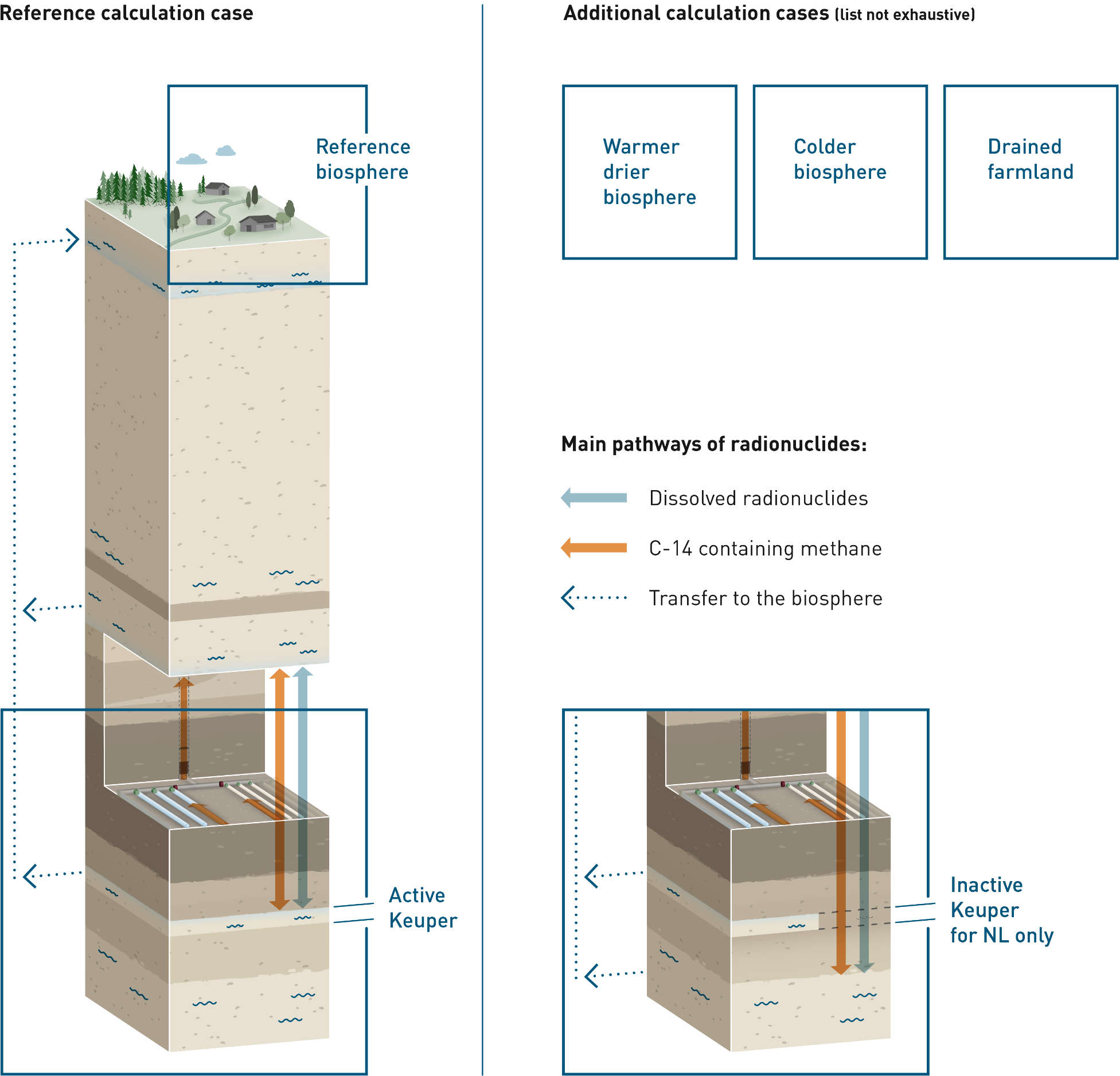
Fig. 7‑3:Main pathways for radionuclide transport in the reference safety scenarios, showing, in the bottom left box, the reference conceptualisation with the hydraulically active Keuper aquifer and, the bottom right box, the variant with the inactive Keuper aquifer below the HLW repository section
The figure also illustrates the different biospheres which are handled as different calculation cases within the reference safety scenario.
Arrows in this and subsequent similar figures indicate, respectively:
Blue, bold: radionuclide migration in the aqueous phase, in which radionuclides are released to porewater that contacts the waste packages and are subsequently transported by aqueous diffusion and, where there is porewater flow, by advection,
Red, bold: radionuclide migration of 14C in the aqueous and gas phases (two-phase flow), in which gaseous radionuclides mix with, and are transported by, repository-generated gas,
Dotted blue arrows: Instantaneous transfer of radionuclides into the regional aquifer within the biosphere, conservatively neglecting the significant transport time with associated radioactive decay.
The modelling approaches used to simulate these migration pathways are summarised in Section 8.1 and described in Appendix B of NTB 24‑18 (Nagra 2024p), and in Chapter 4 of NAB 24‑07 Rev. 1 (Nagra 2024w).
The reference case (RS-RC)15 is a single, deterministic calculation case, with the conservative assumption that the Keuper aquifer is hydraulically active. A reference biosphere based on present-day climatic conditions is assumed. Where there is quantified uncertainty in the properties of repository features, rates of processes and other model parameters, realistic values are assumed (other uncertainties are generally handled using conservative assumptions). Three additional deterministic calculation cases are defined that assume different, though still steady-state, climatic and geomorphological conditions:
-
a warmer and drier climate (RS-BIOS/WARM_DRY),
-
a colder climate (RS-BIOS/COLD), and
-
a drained wetland surface environment (RS-BIOS/DRAINED_FARMLAND).
Further details of the reference and alternative biospheres, and of biosphere modelling in general, are provided in NAB 24-06 (Nagra 2024n).
Additional calculation cases are also defined that aim to identify, illustrate and quantify the impact of uncertainty in the parameters that control radionuclide retention and transport in the repository barriers:
-
a probabilistic calculation case (RS-PROB) with multiple realisations in which all uncertain parameters are randomly sampled from probability distributions, derived from an assessment of parameter uncertainty, to illustrate the range of uncertainty in calculated consequences and to provide the data for a global probabilistic sensitivity analysis to identify those parameters to which the calculated consequences are most sensitive,
-
a deterministic calculation case (RS-CMB) in which all parameters to which the radiological consequences are most sensitive, as identified in RS-PROB, are set to their most unfavourable value within their probability distributions.
Finally, a single deterministic calculation case (RS-KEUPER_INACTIVE) is defined for the variant in which the Keuper aquifer is hydraulically inactive below the HLW repository section.
The alternative safety scenarios relate to uncertainty in the features of the CRZ, namely the possibility that there is either:
-
a hydraulically active confining geological unit, or
-
an undetected fault intersecting the repository.
It is expected that further site investigations for future licensing milestones will reduce the uncertainty concerning these features, and it may then be possible to exclude these alternative scenarios and their variants in future iterations of the post-closure safety case. It is also likely that hydraulically active faults that are currently undetected would be identified during repository construction, and design measures would then be implemented, so as to avoid waste emplacement in their vicinity. However, this countermeasure is disregarded in the current definition of an alternative safety scenario.
The creation of new faults, or the re-activation of existing faults, in the post-closure period by repository-induced effects, i.e., by the effects of repository heat and repository-generated gas, or by geological phenomena, has been shown in the performance assessment in Section 6.3 of NTB 24‑22 Rev. 1 (Nagra 2024u) and in the assessment of earthquake scenarios in NAB 24‑28 (Nagra 2024g) to be either implausible or exceedingly unlikely. It has also been shown that the excavation of the repository by erosive processes is hypothetical within a one-million-year time frame. These effects are, nonetheless, considered in the “what-if?” cases in Section 7.4.
As for the reference safety scenario, we consider the abstraction of the stratigraphic units as illustrated in Sections 5.2.1 and 7.2.2. In line with the geological evidence, the reference safety scenario considers no hydraulically active units within the CRZ. In contrast, in this alternative safety scenario, it is assumed that one of the confining geological units above (variant one) or below the Opalinus Clay (variant two) is hydraulically active. This might be due, e.g., to fractures within the thin, competent “hard beds” (see Section 5.2) having a higher degree of connectivity than currently understood. There are three potentially hydraulically active units within the upper confining geological units, namely Calcareous Malm (CM), Calcareous Dogger (CD), and Sandy-Calcareous Dogger (SCD), and two in the lower confining geological units, denoted by KEU, comprising Argillaceous Keuper and Calcareous Lias, and KAU, comprising Dolomitic and Argillaceous Keuper. In the calculation cases for this alternative safety scenario, each of the above-named units is considered, in turn, to be hydraulically active, while the remainder are inactive, leading to five calculation cases in all (AS-HA/xxx, with xxx being CM, CD, SCD, KEU and KAU).
The assumed hydraulically active unit is conceptualised so as to provide a horizontally connected advective pathway to the regional aquifer. In each of the calculation cases, radionuclides reaching the hydraulically active confining unit can either be transported vertically across them, predominantly by diffusion, or be diverted into the units, in which case they are assumed to be conveyed instantaneously to the biosphere (see Fig. 7‑4). Any 14C reaching a hydraulically active unit in the form of gaseous methane is assumed to dissolve. The fractional distribution of radionuclides continuing vertically or being horizontally diverted is calculated based on flow rates and hydraulic gradients (see e.g., Section B.1.1. in NTB 24-18, Nagra 2024p for details).
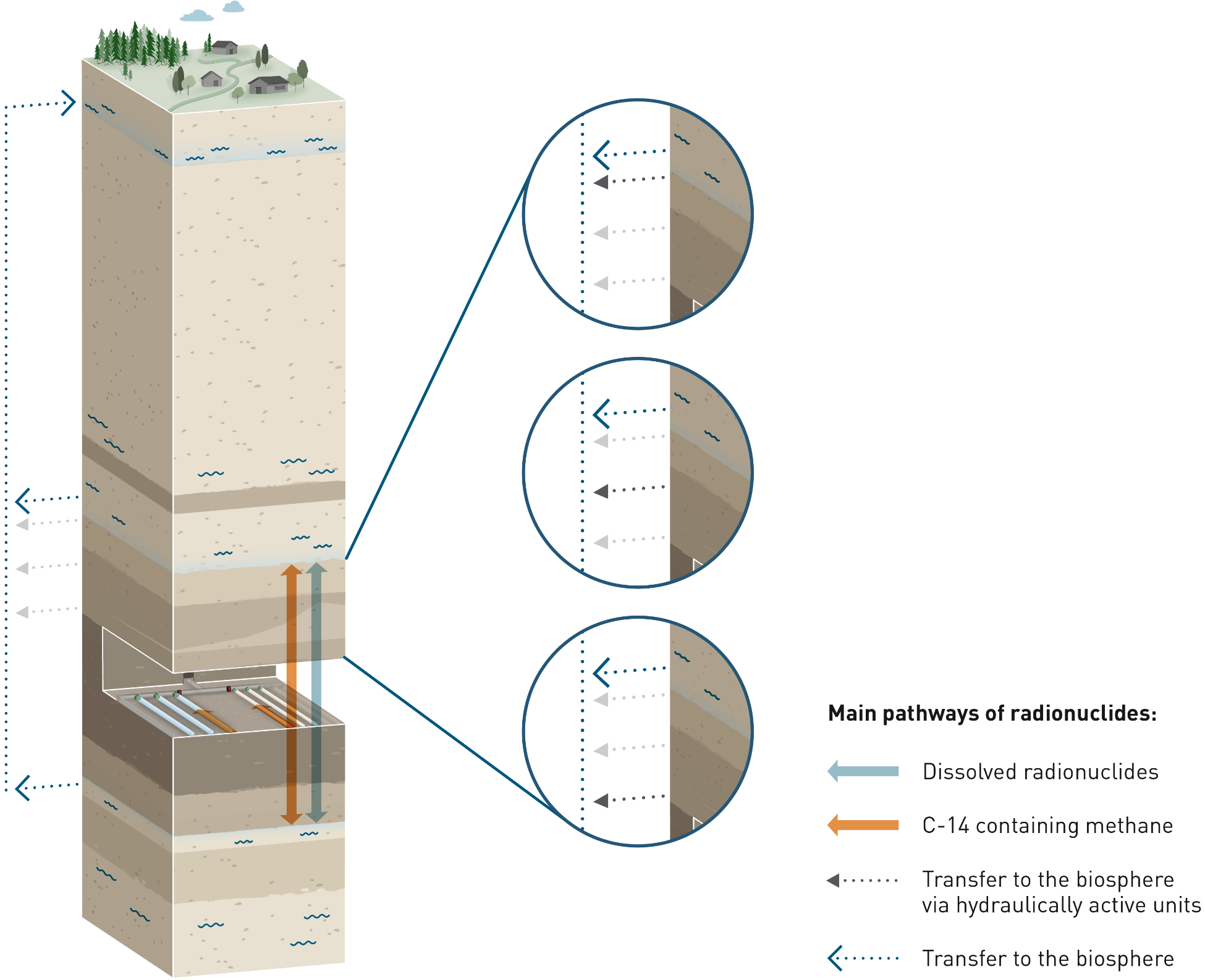
Fig. 7‑4:Main pathways for radionuclide transport where it is assumed that one of the confining geological units above or below the Opalinus Clay is hydraulically active and connected to the regional aquifer and thus provides an additional pathway for the advective transport of radionuclides to the biosphere
This alternative safety scenario assumes the existence of a fault in the vicinity of the repository at the time of its construction that was previously undetected in seismic surveys16. The fault is conservatively assumed to have a transmissivity of 10-10 m2/s. This is one order of magnitude above the highest observed fault transmissivity measured at relevant depths in Northern Switzerland, which occurs in a prominent thrust zone observed in the Schafisheim borehole, well away from the proposed site. Refer to Sections 5.6 and 5.7 of the Geosynthesis of Northern Switzerland in NTB 24‑17 (Nagra 2024i), for detailed discussion.
The fault is conceptualised as a vertical planar feature with a transmissivity that is constant in space and time. Flow of water through the fault is assumed to occur vertically upwards from the deep aquifers underlying the repository (Keuper and Muschelkalk) to the deep aquifer above the repository (Malm). Conceptualising the fault as vertical planar feature with constant properties and connecting the upper and lower deep aquifers is a simplification of reality that is highly conservative.
The vertical Darcy flow in the fault is determined using PA models as described in NAB 24-25 (Nagra 2024k), with a hydraulic gradient of less than about 1 m/m. According to the hydrogeological knowledge described in Section 4.4. of the Geosynthesis of Northern Switzerland in NTB 24‑17 (Nagra 2024i), this assumption is conservative.
Two variants are considered, where the fault intersects the emplaced waste in either the HLW or the L/ILW repository sections. For each variant, two calculation cases are defined. When the fault strike is parallel to the emplacement rooms (cases AS-FLT-HLW-Along and AS-FLT-L/ILW-Along), the fault is assumed to pass through one, single emplacement room. When the fault strike is perpendicular to the emplacement rooms (cases AS-FLT-HLW-Across and AS-FLT-L/ILW-Across), the fault is assumed to pass through all emplacement rooms in the respective disposal area (but not the emplacement rooms of the pilot repository). These different fault configurations are illustrated in Fig. 7‑5.
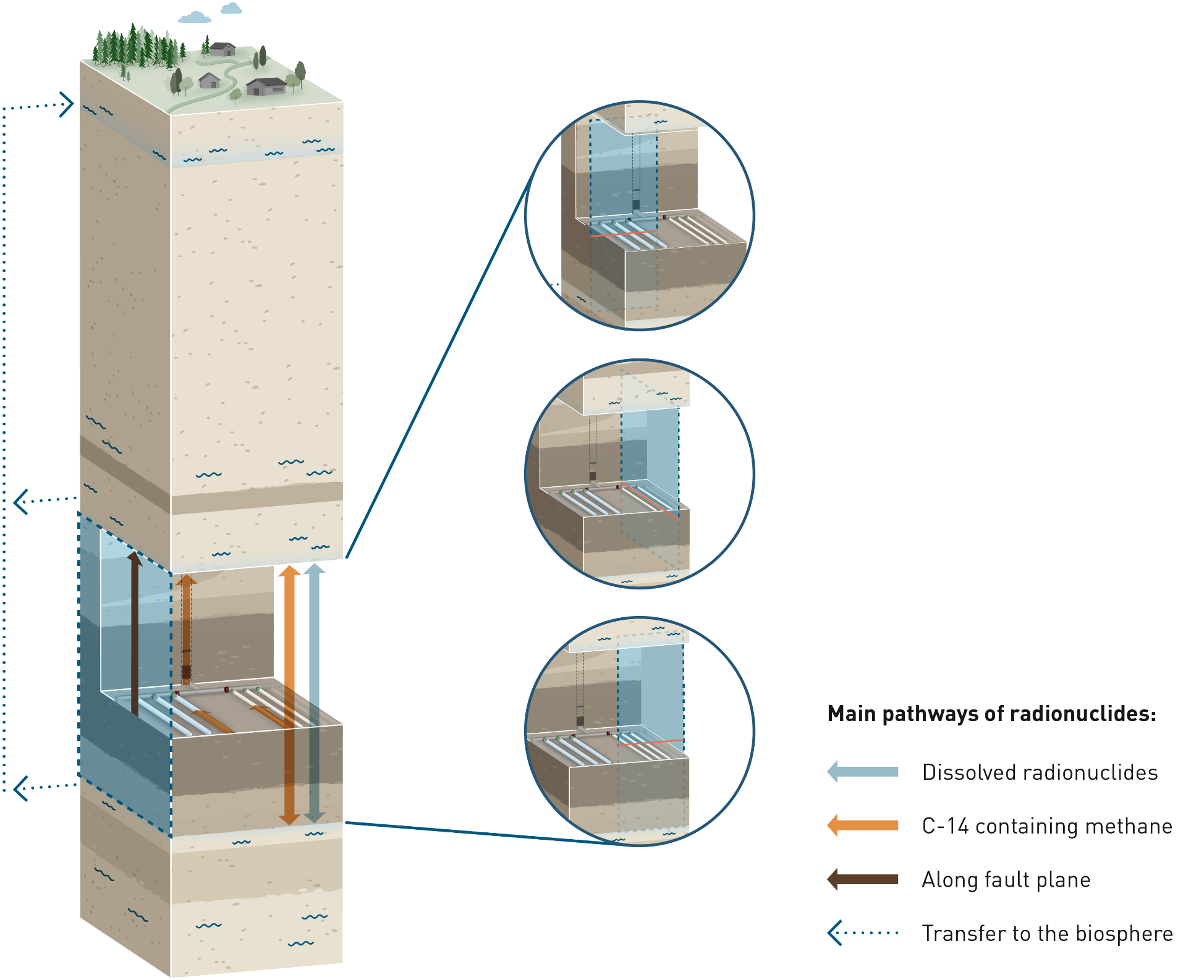
Fig. 7‑5:Pathways for radionuclide transport where the existence of an undetected fault is assumed, which intersects one or more L/ILW emplacement caverns or HLW emplacement drifts
The small inset figures show different ways in which the fault is conceived to impact these repository features in the modelling carried out for the calculation of radiological consequences.
The fact that such a fault would most likely be detected during construction and that technical measures would be implemented accordingly is disregarded in this scenario. ↩
Deviations in performance that are judged to be hypothetical, at least in the one-million-year time period for assessment, may nonetheless be propagated to the analysis of radiological consequences as hypothetical “what-if?” cases, designed to demonstrate the robustness of the repository system. On the one hand, “what-if?” cases can be related to real physical phenomena; such cases are described in Section 7.4.1. On the other hand, Section 7.4.2 presents additional “what-if?” cases that postulate a degraded performance of each of the pillars of safety, unrelated to any physical phenomena.
Three groups of “what-if?” cases related to physical phenomena are described below and considered in the analysis of radiological consequences.
-
Occurrence of an undetected fault with a hypothetically high transmissivity in the vicinity of the repository
This set of “what-if?” cases is almost identical to the alternative safety scenario of an undetected fault but assumes the presence of an undetected fault in the vicinity of the repository with a transmissivity that is much higher than could reasonably be expected: 10‑7 m2/s, which is three orders of magnitude higher than that of the fault considered in the alternative safety scenario described in Section 7.3.2. This is similar to fault transmissivities observed in the thin competent, horizonal limestone features, e.g., the “hard beds”, embedded between more plastic clay rock units within the CRZ; see Section 5.6 of the Geosynthesis of Northern Switzerland in NTB 24‑17 (Nagra 2024i). It is four orders of magnitude above the highest observed fault transmissivity measured at relevant depths in Northern Switzerland, which occurs in a prominent thrust zone observed in the Schafisheim borehole, well away from the proposed site (Section 5.6 of NTB 24-17, Nagra 2024i).
As in the corresponding alternative safety scenario, the fault is represented, for reasons given earlier (Section 7.3.2), as a vertical planar feature with a transmissivity that is constant in space and time. Flow of water through the fault is assumed to occur vertically upwards from a deep aquifer underlying the repository (the Keuper or Muschelkalk) to the Malm aquifer above the repository.
As in the corresponding alternative safety scenario, two variants (fault intersecting either the HLW or the L/ILW disposal area) with two calculation cases each are considered: when the fault strike is parallel to the emplacement rooms (cases WI-FLT-HLW-Along and WI-FLT-L/ILW-Along), the fault is assumed to pass through one, single emplacement room. When the fault strike is perpendicular to the emplacement rooms (cases WI-FLT-HLW-Across and WI-FLT-L/ILW-Across), the fault is assumed to pass through all emplacement rooms in the respective repository section (but not the emplacement rooms of the pilot repositories). These different fault configurations are the same as those shown in Fig. 7‑5.
-
Future creation or reactivation of a fault either by geological processes or as a repository-induced effect after repository closure
A second set of “what-if?” cases is defined that assumes the generation of a new fault or the re-activation of an existing, non-transmissive fault, during the post-closure period. Faulting or fault reactivation are assumed to occur as the result of stress changes induced either by geological processes, such as seismic activity, or by heat or gas generated within the repository. The transmissivity of the fault is again assumed to be 10‑7 m2/s.
As above, the fault is again represented as a vertical planar feature with a transmissivity that is constant in space and time. Flow of water through the fault is assumed to occur vertically upwards from a deep aquifer underlying the repository (the Keuper or Muschelkalk) to the Malm aquifer above the repository.
Again, two variants are considered, where the fault intersects either the HLW or the L/ILW disposal area. The fault is anticipated to be created or re-activated at 10,000 years post-closure in cases where the fault intersects the HLW repository section. The timing corresponds with the assumed canister breaching time, leading to conservative estimations of the consequences. Faulting or fault re-activation could also result in a degraded performance of the bentonite buffer which is considered in these calculation cases. In cases where the fault intersects the L/ILW repository section, 20,000 years is selected, as it is the earliest time when, according to performance assessment, a gas overpressure could occur in the L/ILW emplacement caverns (Fig. 6‑9), again leading to conservative estimations of consequences. There could be damage to the L/ILW near field as a result of faulting/fault re-activation, but this would be unlikely to affect radiological consequences, given that substantial mechanical degradation of the L/ILW cavern backfill cannot, in any case, be excluded by this time and is implicitly assumed in the analysis of radiological consequences, in which the contents of each cavern are assumed to be well mixed.
Finally, for each variant two calculation cases similar to those above are defined: when the fault strike is parallel to the emplacement rooms (cases WI-FLT/RA-HLW-Along and WI-FLT/RA-L/ILW-Along), the fault is assumed to pass through one, single emplacement room. When the fault strike is perpendicular to the emplacement rooms (cases WI-FLT/RA-HLW-Across and WI-FLT/RA-L/ILW-Across), the fault is assumed to pass through all emplacement rooms in the respective repository section (but not the emplacement rooms of the pilot facilities). These different fault configurations are again the same as those shown in Fig. 7‑5.
-
Excavation of the repository by erosive processes
In the very long term, uplift and erosion by both glacial and non-glacial (fluviatile) processes will bring the repository closer to the surface; this phenomenon is included in the reference safety scenario. During the first one million years, the effects on the performance of the repository system are expected to be negligible (Chapters 3 and 6 of NTB 24-22 Rev. 1, Nagra 2024u).
In the more distant future, there is, however, the potential for repository material to be excavated by glacial and non-glacial erosion processes (Section 6.4 of NTB 24-17, Nagra 2024i). In Fig. 7‑6, the erosion processes affecting the rock overlying the repository are shown, with fluvial incision due to the uplift and the evolution of the local topography (e.g., due to hillslope processes) comprising the non-glacial erosion processes.
Even though excavation of the repository by erosive processes is predicted to be possible only after the one-million-year time period for assessment, Nagra is, nonetheless, required by ENSI Guideline ENSI 33/649 (ENSI 2018) to analyse such events as part of the safety assessment. An “excavation of the repository by erosive processes” is thus categorised as a “what-if?” case and analysed in the safety assessment. The conceptualisations and the corresponding analysis of the radiological consequences are described in detail in NAB 24-08 Rev. 1 (Nagra 2024q).
The variants and calculation cases are grouped by the two main erosion processes, glacial erosion and non-glacial erosion:
-
Three variants are defined for the glacial erosion, reflecting the three distinct post-glacial configurations: river, lake, and spring. The river variant is developed into two calculation cases, whereas lake and spring variants have one calculation case each.
-
For non-glacial erosion two variants are defined: erosion of the repository on the hillside and erosion of the repository at the valley floor. The former has four calculation cases (reflecting different hillslope angles), whereas the latter has one calculation case.
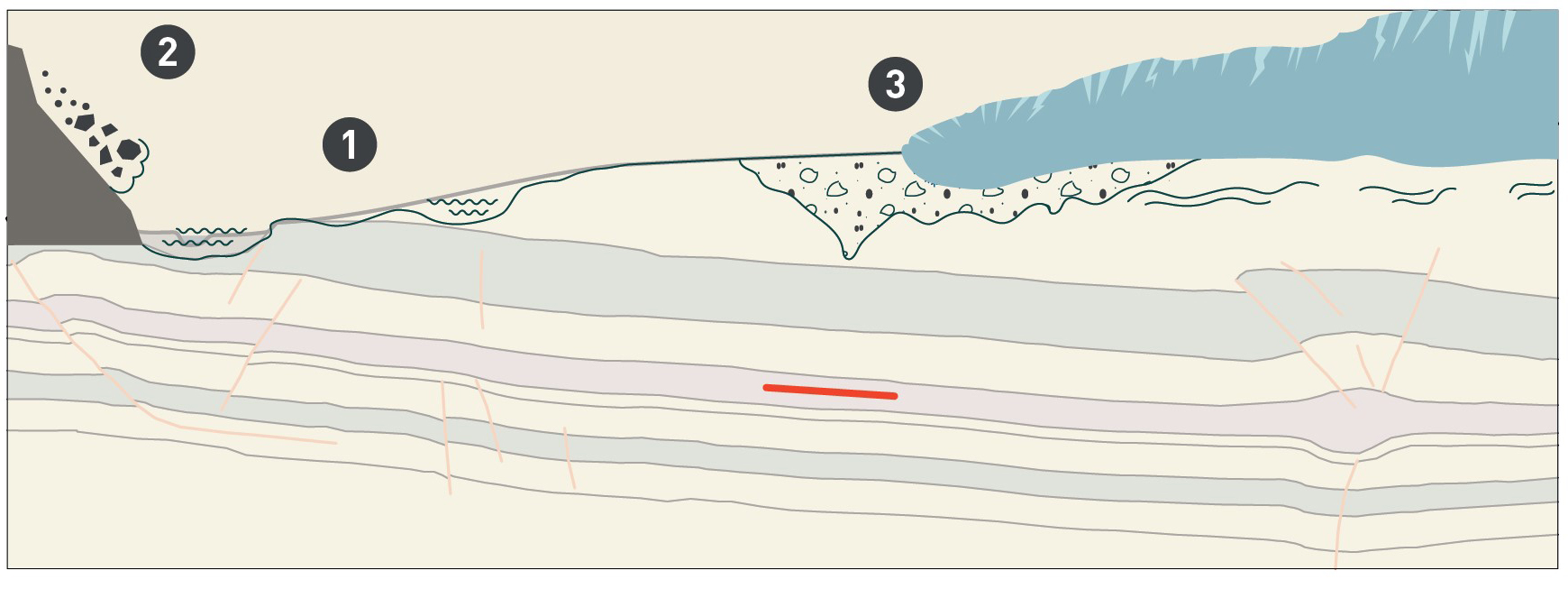
Fig. 7‑6:Illustration of erosion processes affecting the rock overlying the repository (red bar), simplified from Figure 6-1 of NTB 24-17 (Nagra 2024i)
1: Fluvial incision; 2: Evolution of local topography; 3: deep glacial erosion
Further “what-if?” cases are defined and analysed to test the robustness of the system, even in hypothetical situations in which, for no specific cause, certain key favourable features and processes fail to operate as expected or parameter values are assumed that are outside the range considered possible based on current scientific understanding. These cases are developed by systematically going through the pillars of safety17 and either removing them or assuming a degradation of the safety function they serve, as illustrated schematically in Fig. 7‑7.
Each pillar of safety addressed can be considered a variant and, depending on the characteristic of each pillar, several calculation cases are defined and propagated to radiological consequence analysis.
For the CRZ these are:
-
two calculation cases, one with no sorption of radionuclides in the CRZ (WI-CRZ-NOSORB) and another with hypothetically high diffusion coefficients in the CRZ (WI-CRZ-DIFF),
-
two calculation cases with hypothetically high downwardly or upwardly directed hydraulic gradients (WI-CRZ-GRADdown and WI-CRZ-GRADup),
-
one calculation case assuming no upper and lower confining geological units around the host rock (WI-CRZ-NOCONFINING),
-
and a calculation case with hypothetically high radial dimension of the EDZ around the emplacement rooms (WI-CRZ-EDZ).
For the HLW matrices, the calculation cases assume a hypothetically high instant release fraction for radionuclides in spent fuel (WI-SF-IRF), hypothetically high matrix dissolution rates for spent fuel and the glass matrix for reprocessed waste (WI-HLW-DISS) and hypothetically high corrosion rates of spent fuel cladding and other structural parts (WI-SF-CORR).
For the HLW disposal canisters, a calculation case (WI-HLW-CAN) assumes the hypothetical early failure of all canisters after 1,000 years.
For the bentonite buffer in the HLW emplacement tunnels, no solubility limits (WI-HLW-NOSOL) or no sorption (WI-HLW-NOSORB) in the near field and hypothetically high diffusion coefficients (WI-HLW-DIFF) or a hypothetically high permeability of the bentonite buffer (WI-HLW-BUF) lead to four calculation cases.
For the L/ILW cementitious near field, no sorption (WI-L/ILW-NOSORB) and an instant release of all 14C present (WI-L/ILW-C14) are considered.
Finally, the failure of the closure system leads to five calculation cases with hypothetically high permeabilities for the different types and locations of seals: WI-V1-HLW, WI-V1-L/ILW, WI-V2-HLW, WI-V2-L/ILW, WI-V3.
The calculation cases are also summarised in Tab. 8‑8 in Section 8.4.2, where the results are presented and discussed.
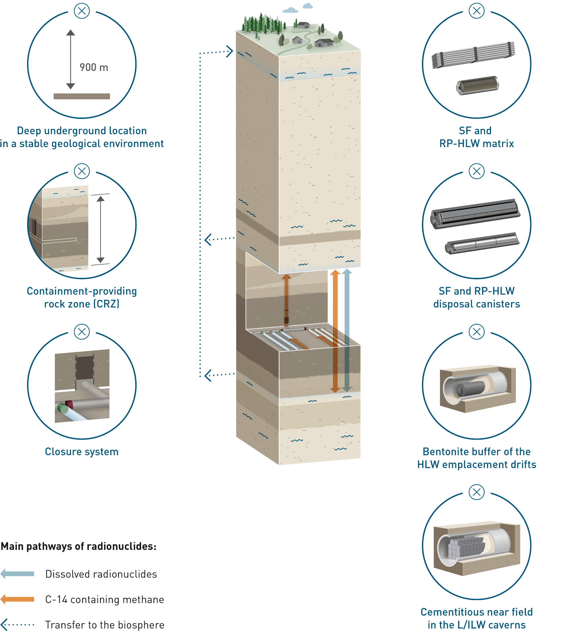
Fig. 7‑7:Schematic illustration of the approach to develop “what-if?” cases postulating a hypothetically degraded performance of the pillars of safety (indicated by “×”)
The only pillar of safety not considered here is a deep underground location in a stable geological environment. The “what-if?” cases related to physical phenomena described in Section 7.5.1 can, however, be seen as examples of the degradation of this pillar of safety. Specifically, if fault re-activation is caused by a large earthquake, this implies a less stable than expected geological environment. Excavation of the repository by erosion processes implies that the deep underground location no longer exists. ↩
The derivation and analysis of future human action (FHA) safety scenarios is described in detail in NAB 24‑09 (Nagra 2024r). Two FHA safety scenarios are formulated and propagated to the analysis of radiological consequences based on a detailed FHA FEP review and discussion.
-
Direct hit by a deep borehole
Drilling a deep borehole is deemed a plausible action at the site that could in principle put humans and the environment at risk. The propagated safety scenario (FHA-1) considers two variants, where the borehole penetrates either an HLW emplacement drift (FHA-1a) or an L/ILW emplacement cavern (FHA-1b), as illustrated in Fig. 7‑8.
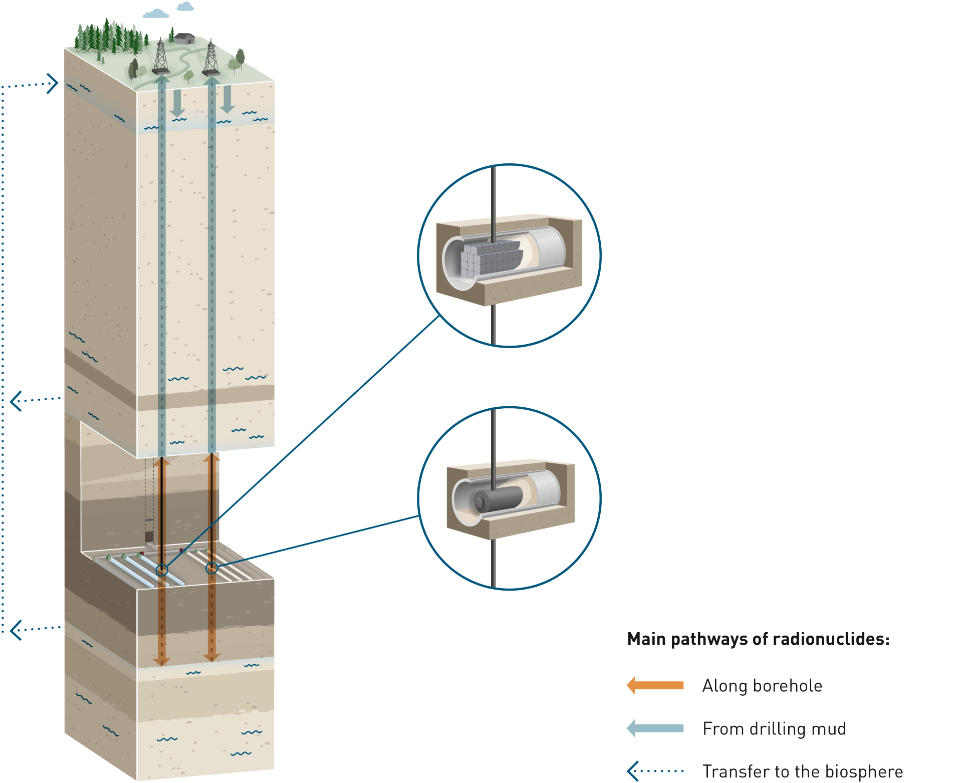
Fig. 7‑8:Pathways for radionuclide transport along boreholes in the FHA-1 safety scenario
The borehole safety scenario assumes a continuous borehole through the CRZ and through either the HLW or the L/ILW repository section down into an underlying deep aquifer to allow for advective flow through the borehole. During drilling, contaminated material could be recovered with the drill mud and, with no knowledge of the possible danger, be disposed of in a gravel pit, from where dissolved radionuclides could enter the local biosphere aquifer. Additionally, deep groundwater and radionuclides could migrate through the borehole, which is assumed to remain open and is assigned various flow rates. Both exposure pathways are considered conservatively in a cumulated way.
For the HLW FHA-1 variant, the borehole is assumed to penetrate an SF disposal canister. The calculation case (labelled as FHA-1a-DH-Diss) assesses the subsequent transport of dissolved radionuclides via the aqueous phase. A two-phase flow calculation that accounts for 14C in the form of methane is performed separately for the situation (FHA-1a-DH-Vol).
For L/ILW, the scenario assumes a borehole penetration of an L/ILW emplacement cavern. Three calculation cases are defined to account for the consequences of a waste package hit as well as for the consequences of penetrating a cavern. One calculation case focuses on a direct hit of a single waste package (FHA-1b-WP-Diss), from which contaminated material could be recovered with the drill mud and disposed of in a gravel pit, from where dissolved radionuclides could be transported to the local biosphere aquifer. The other two calculation cases assume that all radionuclides are homogenously distributed within the cavern and could be released via a preferred pathway along the borehole; one case focuses on the aqueous phase (FHA-1b-PFP-Diss), while the other considers two-phase flow with a focus on 14C in the form of methane (FHA-1b-PFP-Vol).
-
Repository abandonment
This FHA safety scenario (FHA-2) addresses the abandonment of the repository during the monitoring phase, when all waste material is below ground but backfilling, sealing and closure of the tunnels and shafts are incomplete. It is assumed that groundwater entry through the open structures accelerates resaturation and leads to enhanced radionuclide transport through the shafts. Both dissolved radionuclides (FHA-2-Diss) and volatile radionuclide (FHA-2-Vol) are considered. The radiological impact is evaluated for the highly soluble, and dose-dominating, radionuclide I-129, and the volatile form (methane) of 14C.