
6. Performance assessment (NTB 24-10)
Aims of the chapter:
- To describe performance assessment (PA), which provides an evaluation of the functionality of each barrier component and of the entire system, and that covers the expected evolution and uncertainties.
- To develop arguments that support the claims of the safety concept.
- To systematically assess uncertainties and manage uncertainties during PA.
- To screen the PA outcome in order to identify potentially safety-relevant deviations in performance as input to safety scenario development.
- To ensure that potential lines of evolution, scenarios, and variations in performance are comprehensively covered.
Performance Assessment (PA) represents the first stage in the general safety assessment workflow aimed at producing a robust post-closure safety case. Following international standards of transparent and traceable assessment workflows (OECD/NEA 2004), PA addresses the post-closure safety of the repository at a level of simplification that bridges the gap between the real-world system and its highly abstracted representation in the analysis of radiological consequences.
The auditability of the assessment workflow is ensured with a traceable method of proof. For this, claims are formulated, assigning one or more safety functions to each component of the multi-barrier system and to the repository system as a whole. The claims are substantiated by a suite of arguments. A claim can be said to be robust if it is well substantiated using sound arguments, which are themselves supported by convincing evidence, such as: (i) empirical knowledge, including experience from other waste management programmes, (ii) dedicated scientific and technical databases that have been elaborated specifically in the context of the repository project and (iii) a safety-oriented repository design.
Traceable handling of uncertainty is an indispensable element of PA and of overall safety assessment. As part of uncertainty management, PA provides evidence that the modelling tools and approaches applied in the quantitative assessment of barrier performance at component and total-system levels adequately represent the safety relevant processes and phenomena.
It is the role of PA to screen the possible paths of repository performance and to identify safety-relevant deviations from expected repository performance as input to the development of safety scenarios for radiological consequence analysis. From the PA perspective, the possible paths of repository evolution are classified in terms of expected performance of the multi-barrier system and deviations thereof.
Performance assessment workflow
Fig. 6‑1 shows how PA is positioned within the workflow for the post-closure safety case, highlighting, in the orange box, the main elements of the performance assessment process. These elements comprise:
-
an assessment of barrier performance for each of the pillars of safety of the multi-barrier system,
-
an assessment of the entire system (total system performance), to account for thermo-hydro-mechanical and chemical (THM-C) interactions between the individual barrier components,
-
an assessment of uncertainties associated with the simplified representation of the real-world repository system in an abstracted PA framework (uncertainty propagation associated with the abstraction process), and
-
an assessment of deviations from expected repository performance by barrier and by interaction (“screening of assessment scenarios”).
The key phenomena relevant to the evolution and performance of the repository system are considered in the PA, including those that could lead to deviations from expected repository performance.
These phenomena are identified in NAB 24-20 Rev. 1 (Nagra 2024m), which synthesises Nagra’s understanding of the initial state and expected post-closure evolution of the repository. As noted in Section 4.5, this understanding has developed iteratively over many years, with each iteration having been peer-reviewed and informed by Nagra's extensive RD&D programme.
The key phenomena identified in NAB 24-20 Rev. 1 (Nagra 2024m), their relevance to system evolution and performance, and their potential to lead to performance deviations are listed in App. B (Tab. B‑1). This appendix also indicates the sections of the PA synthesis NTB 24-22 Rev. 1 (Nagra 2024u) where these phenomena are addressed.
Assessment of barrier performance and of the performance of the total system employs a combination of qualitative argumentation and quantitative analyses. The latter can involve the evaluation of performance metrics or indicators, considering all identified sources of uncertainty, and a comparison of these metrics or indicators with performance targets or evaluation scales. Performance targets, if met, may then indicate, for example, that uncertainties do not compromise the expected performance of a barrier or of the total system.
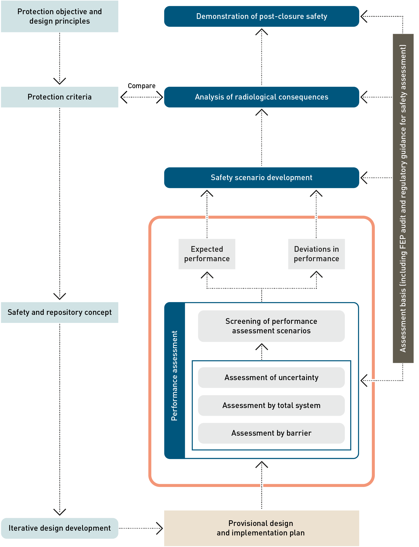
Fig. 6‑1:Workflow for the post-closure safety case, highlighting, in the orange box, the main elements of the performance assessment process
The current safety and repository concept is set out in Chapter 3. The main barriers and other features contributing to the safety functions are termed “pillars of safety”. Fig. 3‑3 and Fig. 3‑4 illustrate schematically how the pillars of safety contribute to the various safety functions. PA provides detailed descriptions of the pillars of safety and their intended functionalities under relevant conditions.
In PA, the expected performance of the multi-barrier systems is expressed in terms of a set of claims concerning the contribution of each component of the multi-barrier system and of the repository system as a whole to the repository safety functions, in line with the current safety concept. Each claim is formulated based on, and examined through, a comprehensive analysis of empirical data, experimental results and modelling evidence. The most important claims, arguments, and evidence in the assessment of the individual pillars of safety (assessment by barrier) are presented in the following sections. A more detailed discussion of the corresponding claims, arguments, and evidence is given in Chapter 3 of NTB 24‑22 Rev. 1 (Nagra 2024u).
The deep underground location of the repository in a setting that is not at risk of disruptive geological events and processes and with all access routes sealed ensures that the radioactive waste is safely enclosed for a very long time. Careful selection of a favourable repository site at a suitable depth contributes to the safety functions of isolation of radioactive waste from humans and the environment, immobilisation, retention and slow release of radionuclides and long-term stability of the repository system regarding the long-term geological and climatic evolution, encompassing erosion, neotectonics, and glaciations. The favourable overall geological setting of the repository guaranties stable conditions over geological time periods.
The CRZ encompasses several complementary barrier elements, addressed in PA as separate assessment objects, each of them contributing to one or several safety functions of the geological barrier. The Opalinus Clay represents the diffusion-dominated primary geological barrier and provides long-term confinement of the waste, ensuring a stable geochemical and geomechanical environment. The upper and lower confining geological units serve as additional transport barriers.
The geological barrier, in particular the Opalinus Clay, has been subjected to extensive investigations for more than 20 years, comprising empirical studies and dedicated site investigations, with flow and transport experiments at a borehole scale and at a core scale and including experiments within the scope of Nagra’s recent deep drilling campaign as described in the geosynthesis report NTB 24‑17 (Nagra 2024i). There is ample evidence that the intact Opalinus Clay represents a diffusion-dominated transport barrier with sufficient vertical and lateral extent and that the confining units also have favourable properties.
The diffusive properties of the Opalinus Clay and the confining units are well characterised as documented, e.g., in NTB 23-08 (Glaus et al. 2024a) and NAB 23-26 (Van Loon et al. 2024).
Excavation Damage Zone (EDZ)
A large body of evidence exists, showing that the shape, extent, and characteristics of the EDZ in the Opalinus Clay around the HLW emplacement drifts and the L/ILW emplacement caverns impairs the barrier functions of neither the CRZ nor the engineered barriers. The following points summarise the main arguments (for details, see Section 3.3.3 in NTB 24‑22 Rev. 1, Nagra 2024u):
-
the choice of the excavation method and tunnel support limits the extent of the EDZ, such that it does not significantly impact the transport distance of radionuclides through the Opalinus Clay,
-
simulations show that the resealed EDZ around the HLW drifts and L/ILW caverns does not represent a significant axial transport path for dissolved radionuclides, the possibility of which is, in any case, minimised by the dead-end architecture of the HLW drifts and L/ILW caverns,
-
the hydromechanical evolution and self-sealing of the EDZ limits microbial activity,
-
the higher porosity within the EDZ around the HLW drifts and L/ILW caverns provides an additional storage volume for repository-generated gas, further limiting gas pressure build-up,
-
the existence of an EDZ around the HLW emplacement drifts reduces the loads on the drift lining (Geomechanica Inc. 2025), and
-
the evolution of the EDZ around the backfilled emplacement rooms in response to eventual failure of the lining is limited, because the swelling pressure of the bentonite and the low compressibility of the L/ILW backfill compensates for the loss of strength of the lining.
SF and its cladding
SF and its cladding, which are illustrated in Fig. 6‑2, ensure the immobilisation, retention and slow release of radionuclides. Under repository conditions, SF, which mainly consists of UO2, is chemically stable. Due to its very slow dissolution rate, it does not impair the chemical integrity of the canister or of the bentonite buffer. The main arguments supporting this claim are:
-
the SF pellets and the surrounding cladding are chemically stable and do not chemically interact with the canister and bentonite, or do so only to a very limited extent (Section 9.2 in NTB 23-02 Rev. 1, Nagra 2024v and Chapter 5 in NAB 23-10, Johnson et al. 2023)
-
the majority of radionuclides are retained within the UO2 and MOX mineral phases (Kleykamp 1985, Thomas et al. 1992, Walker et al. 1996, Johnson et al. 2023 and references therein),
-
the most rapidly released fraction of the radionuclide inventory of SF (the instant release fraction, or IRF) is small compared with the total radionuclide inventory (Section 4.2.1 in NTB 23-02 Rev. 1 Nagra 2023b and Chapter 1 in NAB 23-10, Johnson et al. 2023), and
-
following canister breaching, most of the radionuclides will be released only slowly due to limited solubility of the waste matrix and low degradation and dissolution rates after water has entered the canister (Cui et al. 2010, Ekeroth et al. 2020, Spahiu 2021, Nagra 2024v, Johnson et al. 2023 and references therein).
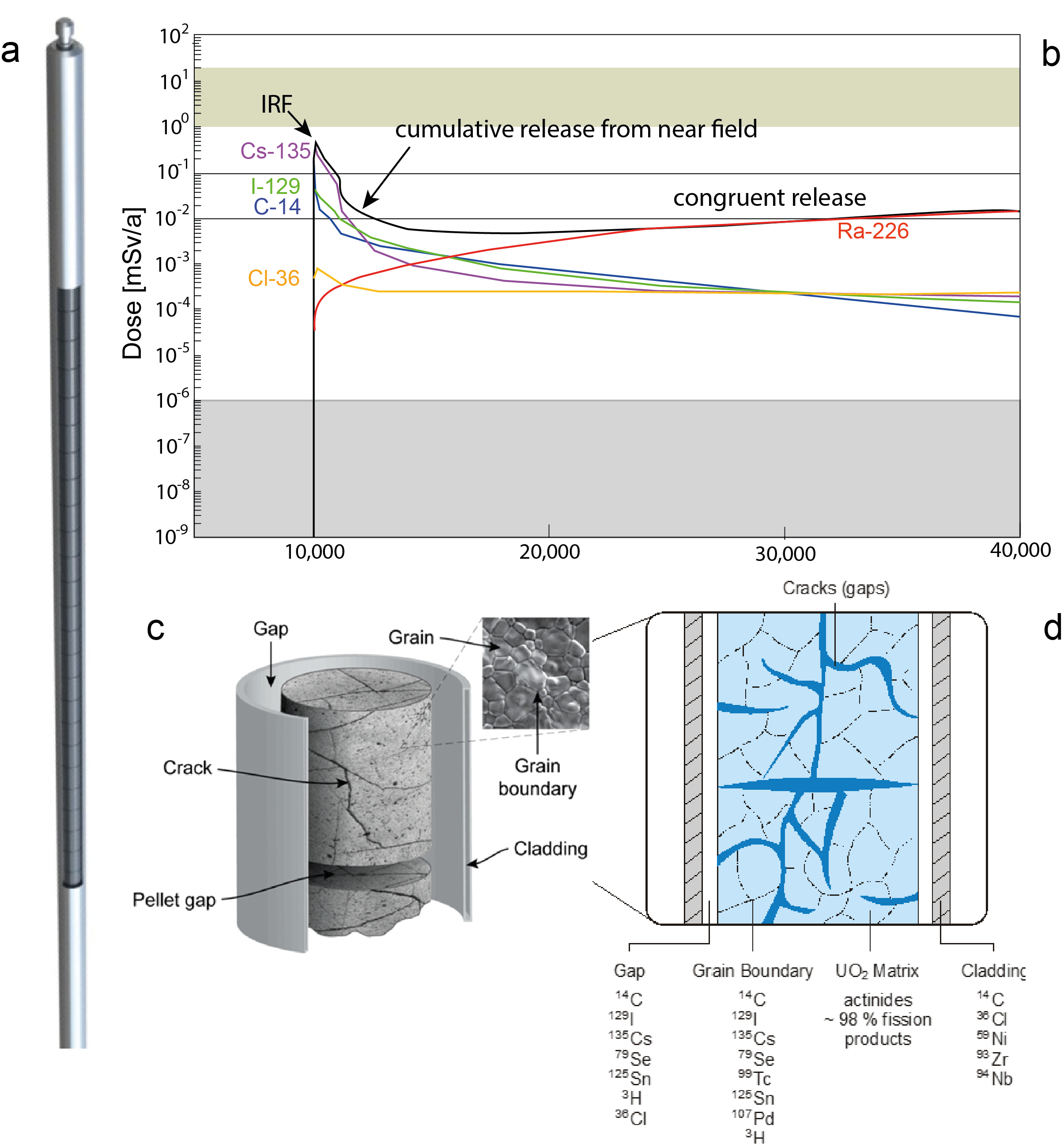
Fig. 6‑2:Main elements of the spent fuel that are assessed
a) Schematic view of a fuel rod, illustrating fuel pellets in Zircaloy cladding. b) Illustration of radionuclide release rates from the spent fuel following canister breaching, converted to dose rates using biosphere dose conversion factors. c) The macro and micro-structure of a fuel pellet after its irradiation. d) conceptual distribution of radionuclides in a spent fuel rod (from Johnson 2014, redrawn after Johnson & Tait 1997).
RP-HLW
RP-HLW (Fig. 6‑3) contributes to the immobilisation, retention and slow release of radionuclides. Under repository conditions, RP-HWL is chemically stable and does not impair the chemical integrity of the canister or of the bentonite buffer. RP-HLW is the product of the treatment and reprocessing of SF, which is carried out to extract fissionable U and Pu for re-use in NPPs. Research on RP-HLW has been performed for decades and has been followed by Nagra, e.g., in the scope of the NF-PRO projects (e.g., Grambow et al. 2008). Current understanding of the aqueous dissolution of RP-HLW and of the rates at which this process occurs have been synthesised in NAB 23-09 Curti (2022). The borosilicate glass matrix of the RP-HLW provides a chemical environment in which most radionuclides are immobilised and are released very slowly. This is mainly due to the chosen glass composition and to the formation of a passivation layer, which provides a barrier that protects the glass from dissolution (Gin et al. 2016, 2020a,2020b, Nagra 2024v, Curti 2022 and references therein).
The stainless-steel flasks containing the RP-HLW are compatible with the glass, the disposal canister and the bentonite, mainly due to limited chemical interactions (Section 9.3 in NTB 23‑02 Rev. 1, Nagra 2024v).
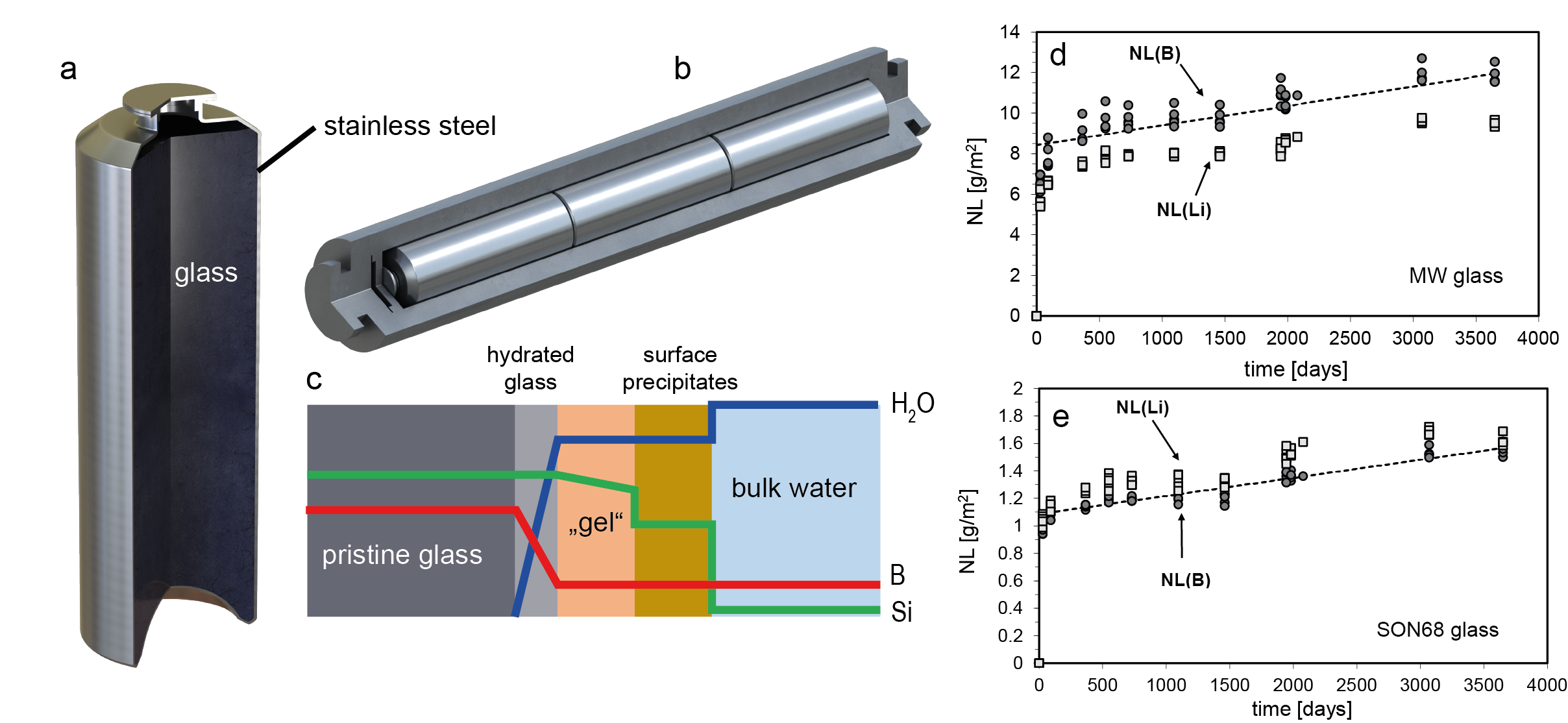
Fig. 6‑3:Main elements of the vitrified waste from reprocessing that are assessed
a) Stainless steel flask for RP-HLW. b) Disposal canister for 3 RP-HLW flasks. c) Schematic cross section through altered borosilicate glass in contact with the leaching aqueous solution, showing idealised profiles for Si, B and water concentrations. d) and e) Normalised mass loss for the non-active borosilicate glass “MW” and “SON68” glass determined from long-term experiments at PSI, Switzerland, (from Curti 2022).
The SF and RP-HLW disposal canisters (Fig. 6‑4) provide complete containment of radionuclides for at least the early post-closure phase, when the HLW near field is exposed to distinct thermal and hydraulic disequilibrium conditions. The main arguments are that:
-
the canister has been designed such that structural integrity is ensured for at least the minimum 1,000 years required by regulations, even under the assumption of unfavourable corrosion rates, material degradation and external state conditions (Section 4.3 in NTB 24‑20, Nagra 2024d).
-
manufacturing, welding, heat treatment, inspection and handling procedures can be tailored to minimise the occurrence of undetected defects and residual stresses (Chapter 3 in NTB 24‑20, Nagra 2024d), and
-
the gas production rate due to corrosion of the canisters is limited compared with the gas storage and transport capacity of the rock and repository structures, such that excessive pressure build-up in the repository, is avoided (Nagra 2024o).
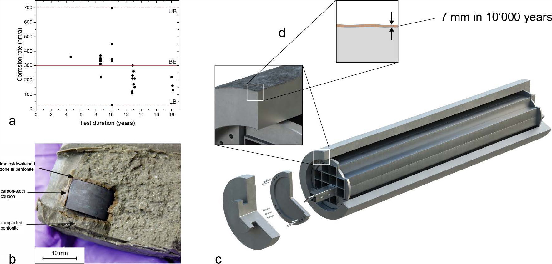
Fig. 6‑4 Illustration of a disposal canister for SF and RP-HLW. A canister lifetime of at least 1,000 years is ensured by appropriate design even under the assumption of unfavourable corrosion rates
(a) Laboratory measurements of steel corrosion rates in anaerobic bentonite saturated with artificial Opalinus Clay porewater as part of Nagra’s RD&D programme (Diomidis & Reddy 2022). (b) In-situ experiments at the Mont Terri rock laboratory confirm the low corrosion rates (Diomidis & Reddy 2022). (c) SF canister design (Nagra 2024d). (d) A corrosion depth of about 7 mm in 10,000 years under in-situ conditions is expected (Nagra 2024d).
Furthermore, the products of canister degradation (corrosion) are not detrimental to other engineered or geological barriers, because chemical interactions between corrosion products and the buffer do not significantly reduce its function as a hydraulic barrier (Section 8.2.3 and Appendix A in NTB 23-02 Rev. 1, Nagra 2024v).
The properties of the bentonite buffer (Fig. 6‑5) have been extensively investigated (e.g., Nagra 2019, Leupin et al. 2014, Seiphoori 2015), resulting in a large body of evidence supporting safety-related claims. In particular, the following contribute directly or indirectly to the efficient retention of any radionuclides released following canister breaching:
-
the inherently low hydraulic conductivity of the buffer at full saturation,
-
its self-sealing ability,
-
its marked sorption capacity,
-
the micro-porous environment that it provides at full saturation, and
-
its ability to transport gas without fracturing.
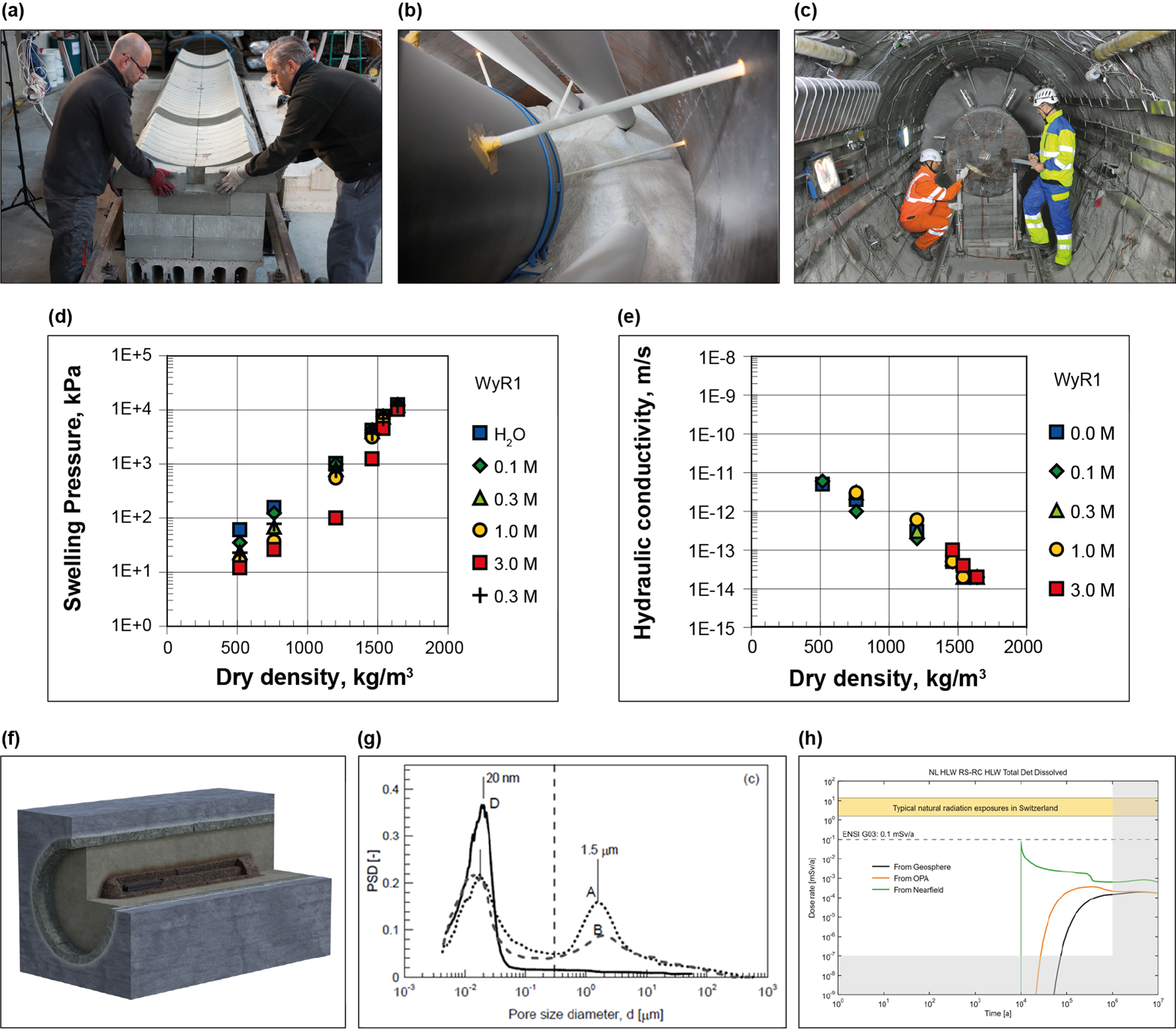
Fig. 6‑5:Bentonite buffer, which has been extensively investigated in small- and large-scale experiments over the last few decades
The handling and emplacement of the bentonite buffer have been successfully demonstrated at a large scale (a-c). It has been shown that the hydraulic properties and the swelling pressure are related to the emplaced dry density (x-axis of (d) and (e); Karnland et al. 2006) and that these properties are not significantly affected by the expected thermohydraulic evolution of the near field (Leupin et al. 2014). The interfaces with the canister and with the cementitious rock support (lining) evolve very slowly as these processes are limited by diffusion (f). The evolving interfaces do not impair the functionality of the bentonite buffer or of the host rock. Upon saturation the pore-size distribution is shifted due to the swelling processes towards nanopores (g) (Seiphoori et al. 2014), a key process defining macro properties such as hydraulic conductivity. The excellent retention properties of bentonite are an important contributor to limiting the radionuclide flux into the host rock (h).
The bentonite buffer has also been shown to provide favourable environmental conditions contributing to the longevity of the HLW canisters by providing a long-lasting, mechanically homogeneous, and chemically favourable interface. The microporous environment within the buffer provides sufficient limitation of microbial activity, and the buffer conducts heat sufficiently well. The waste package, canister, and buffer thus do not experience conditions detrimental to the performance of their safety functions (Nagra 2019).
The geomechanical and the chemical evolution of the cementitious lining around the HLW emplacement drifts do not significantly impair the functionality of any engineered and geological barriers. Specifically, the loss of strength of the lining does not significantly affect the safety functions of the buffer or the intended lifetime of the canister and does not significantly affect the extent and hydraulic properties of the EDZ (Geomechanica Inc. 2025). Indeed, experimental evidence shows that chemical interactions of the lining with the bentonite buffer are spatially limited and thus do not significantly affect the safety functions of the buffer EDZ (Geomechanica Inc. 2025). Indeed, experimental evidence shows that chemical interactions of the lining with the bentonite buffer are spatially limited and thus do not significantly affect the safety functions of the buffer (Chapter 3 in NAB 22-34, Prasianakis et al. 2022 and Yokoyama et al. 2021). These findings are supported by reactive transport modelling (Section 6.7.2 in NTB 23-02 Rev.1, Nagra 2024v, for details about the models see NAB 23-33, Kosakowski 2023).
The major components within the L/ILW near field are cement-based, compatible with each other and contribute to an alkaline environment upon contact with water from the Opalinus Clay (Sections 3.3 – 3.5 and Appendix A in NTB 23-03, Kosakowski et al. 2023 and Chapter 5 in NAB 20-11, Kosakowski et al. 2020 and references therein).
The cementitious near field contributes to the retention of radionuclides because, by design, the cement paste contains C-S-H phases that sorb radionuclides (Nagra 2021c, 2024u, Tits & Wieland 2023, Kosakowski et al. 2023).
The concrete disposal containers and cementitious container infill mortar contribute to the initial structural integrity of the waste packages because:
-
by design, the concrete containers are reinforced and constructed of high-quality concrete, and
-
filling of the disposal container with a container infill mortar contributes to limiting void space within the L/ILW cavern.
The grain-supported cavern backfill mortar (Fig. 6‑6) contributes to the mechanical integrity of the L/ILW caverns by filling the void space and because, by design, the backfill mortar has grain-to-grain contact (Jacobs et al. 1994, Nagra 2021a, Nagra 2024u).
Finally, the porosity and chemical composition of the cavern backfill mortar contributes to the compatibility of the multi-barrier system. Specifically, the backfill mortar provides storage volume for repository-generated gas and a continuous porosity to transport that gas (Nagra 2024o). The highly alkaline conditions present in the backfill and throughout the near field also limit gas production by supressing corrosion rates and microbial activity (Section 3.1.2 in NTB 21-02, Nagra 2021a; Section 3.3.1 in NTB 23-03, Kosakowski 2023; Chapter 6 in NTB 13-04, Warthmann 2013 and Section 3.4.3 in NTB 24-22 Rev. 1, Nagra 2024u).
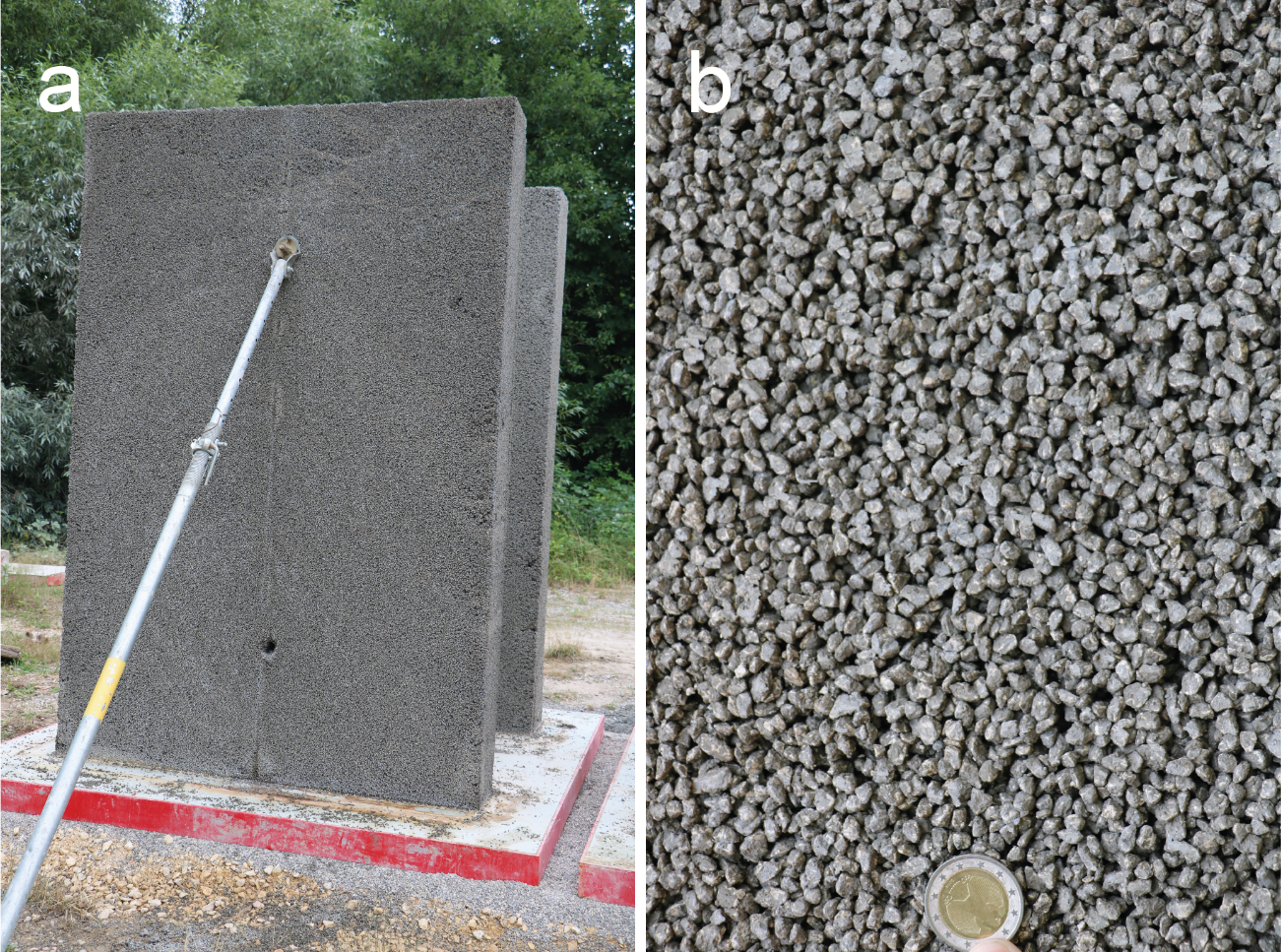
Fig. 6‑6:Grain-supported cavern backfill mortar for the L/ILW caverns
The figure shows results from a large-scale test of backfilling techniques and properties of the mortar.
As described in Section 3.3, the V1-HLW seal ensures the mechanical and chemical integrity of the bentonite buffer, because, by design, the seal prevents buffer erosion and saturation and is constructed mostly of materials that are in chemical equilibrium with the surroundings (Section 4.2 in NAB 21-12 Rev. 1, Nagra 2021b and Chapter 6 in NAB 23-21, Martin et al. 2023). The V1-HLW seal also contributes to a retarded release of dissolved and volatile radionuclides, being designed in such a way that gas release along the EDZ and lining is limited (see Section 5.3 in NAB 21-12 Rev. 1, Nagra 2021b).
The V2-HLW seal contributes to a retarded release of radionuclides and prevents any safety-relevant interaction between the HLW and L/ILW repository sections (Section 2.1 in NTB 24-23, Nagra 2024o and Section 1.2 in NAB 23-21, Martin et al. 2023) due to a design that limits the transport of volatile and dissolved radionuclides after full saturation of the seal. The V1-L/ILW and V2-L/ILW seals also contribute to a retarded release of dissolved radionuclides from the L/ILW emplacement caverns. Since the permeability of the seals is low, transport of dissolved radionuclides across the sealing elements predominately occurs by diffusion (Chapter 5 in NAB 23-21, Martin et al. 2023).
Both, the V1-L/ILW and V2-L/ILW seals also contribute to the compatibility of the barrier components because:
-
the low gas entry pressure of the sand-bentonite mixture used in the sealing elements ensures efficient gas release (see Section 3.5 in NTB 16-07, Manca 2016), preventing the occurrence of damaging gas overpressures (Chapter 6 in NTB 24-23, Nagra 2024o), and
-
chemical interactions between the materials used in the closure system and the surrounding Opalinus Clay are limited (Section 2.3 and Chapter 3 in NAB 22-24, Prasianakis et al. 2022; Chapter 6 in NAB 23-21, Martin et al. 2023; Chapter 6 in NTB 23-02 Rev. 1, Nagra 2024v and Section 3.3.4 in NTB 23-03, Kosakowski et al. 2023).
The V3 shaft seal contributes to the isolation of radioactive waste from the biosphere because, by design, the hydraulic conductivity is so low that radionuclides are only released by diffusion across the V3 seal. Thus, the V3 seal limits the release of dissolved and gaseous radionuclides because, by design, the transport of gaseous and dissolved radionuclides is largely prevented after full saturation of the seal (Section 7.2.2 in NAB 23-21, Martin et al. 2023 and Chapter 6 in NTB 24-23, Nagra 2024o). Furthermore, the V3 seal together with the deep geological location, makes inadvertent intrusion unlikely and also contributes to isolating the repository from events at the surface
The VF1 and VF2 backfills provide gas storage volumes that contribute to a low gas-pressure build-up, and, given their low hydraulic conductivity, delay and limit water flow into the operations tunnel. The stiff backfills also contribute to the mechanical integrity of the host rock by providing mechanical support. Finally, because of their clay content, the VF1 and VF2 backfills contribute to the retardation of radionuclide release along the tunnel system (Section 3.2 in NAB 21-12 Rev. 1, Nagra 2021b and Section 2.2.4 in NAB 23-21, Martin et al. 2023).
Further PA claims are formulated for the performance of the repository system as a whole, including repository-induced processes and phenomena that develop over spatial scales covering multiple barriers. The most important claims, arguments and evidence in the assessment of the total system are presented in the following sections. A more detailed discussion of these and other claims, arguments and evidence is given in Chapter 4 of NTB 24‑22 Rev. 1 (Nagra 2024u).
In NTB 24‑22 Rev. 1 (Nagra 2024u), numerical simulations are used to judge the performance of the repository using predefined performance targets. Critical aspects considered in these simulations include, for example, the integrity of the multi-barrier system, scenarios for the potential release of radionuclides, thermal and gas-related factors, and geological attributes. The simulations rely on conceptualisations of geological and hydrogeological conditions. Based on the geological characterisation described in the geosynthesis report NTB 24‑17 (Nagra 2024i) and references therein, it is assumed in these conceptualisations that diffusion is the dominant transport mechanism in the CRZ, with advective transport along steeply dipping faults not being relevant. Sedimentary features, such as hard beds in the upper and lower confining units, do not act as lateral release paths.
Critical aspects noted above are screened for their relevance to repository performance with a model-based assessment that uses a code capable of coupling thermal and hydraulic processes (e.g., TOUGH). Parametric uncertainty is considered probabilistically through Monte Carlo simulations. This necessitates a model setup with simplified representations of complex coupled processes to ensure that the demands on computational resources are manageable.
Findings from extensive 3D simulations confirm decoupling between HLW and L/ILW repository sections, allowing independent analysis. Consequently, separate model setups are employed for each repository section. Performance indicators include temperature (T) and pore pressure (P) at specific points, as well as the fluxes of tracers (F) representing conservative dissolved and volatile species, which are crucial for assessing safety functions related to radionuclide immobilisation and barrier integrity.
The total system performance depends on the thermohydraulic (TH) evolution of the repository system. Detailed TH analyses are described in NTB 24‑22 Rev. 1 (Nagra 2024u) and NAB 24‑25 (Nagra 2024k) and the results are summarised briefly in the following paragraphs.
Fig. 6‑7 shows temperature transients simulated with a 3D repository model over a one-million-year period, including the construction, ventilation14, and post-closure phases. In HLW emplacement drifts, temperature spikes due to heat-generating waste, then decreases back to ambient temperature. Sections of the operations tunnel near the emplacement area also see temperature increases due to their proximity. In the L/ILW emplacement caverns, temperature returns from the relatively low values caused by ventilation to ambient within ~ 3,000 years and does not exceed it. The central repository area (not shown in the figure) shows no significant temperature changes due to heat generated by HLW.
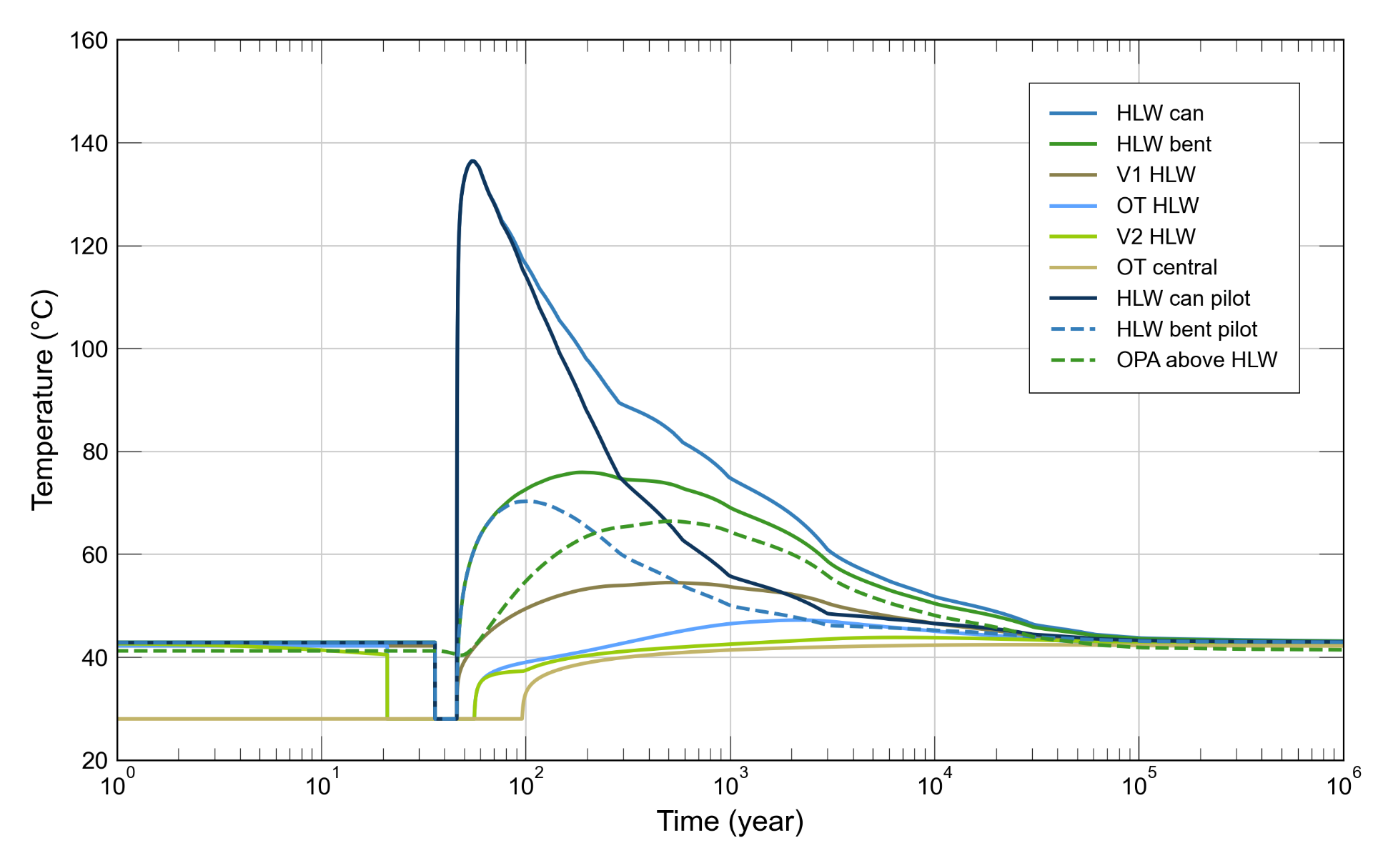
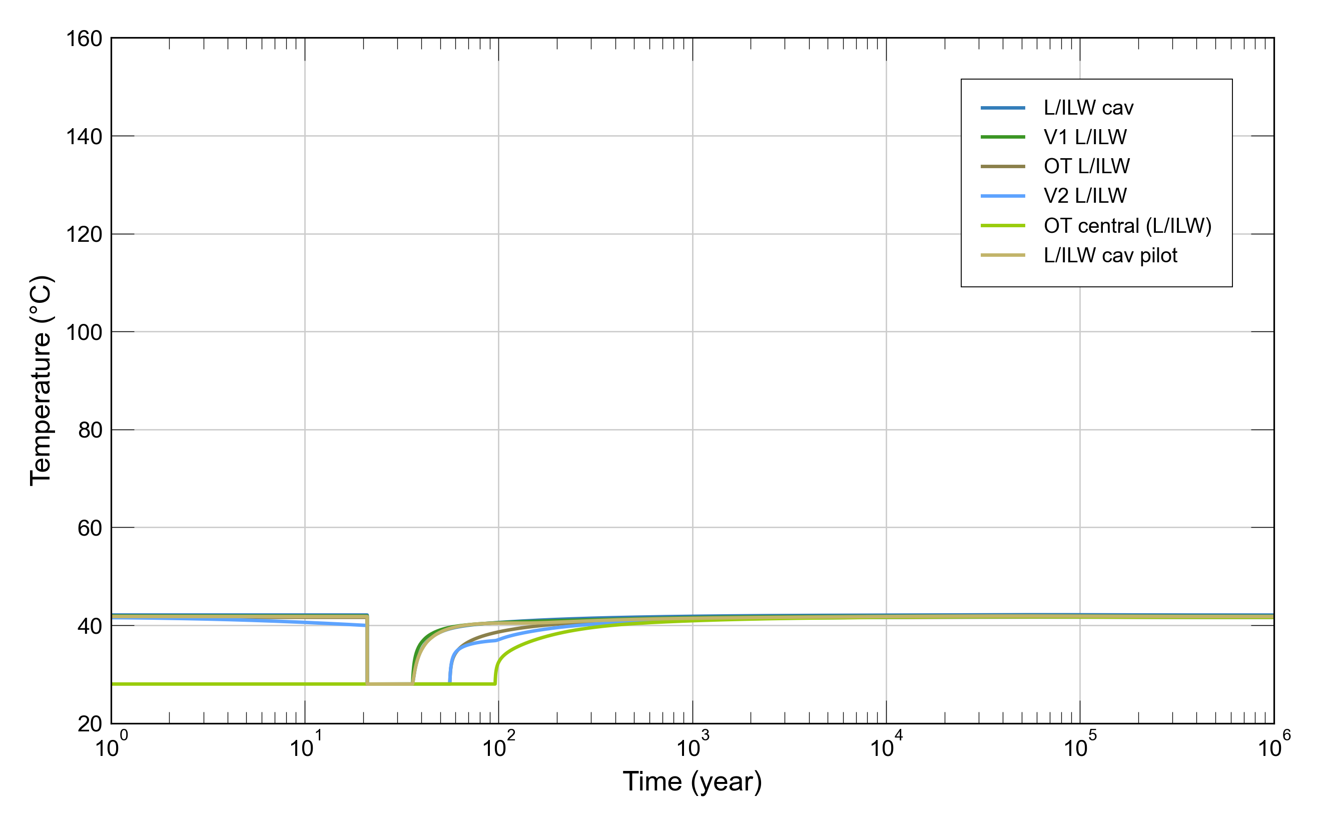
Fig. 6‑7:Assessment of total system: transients of temperature in the HLW repository section (top) and in the L/ILW repository section (bottom)
V1: cavern or drift seal, OT: operation tunnel, V2: repository section seal, pilot: pilot facility. For more details see Section 5.3 in Nagra 2024o.
Fig. 6‑8 shows gas saturation transients from the same simulation. In the HLW repository section (top figure), local gas saturation depends on the backfill material. The operations tunnel, backfilled with high-porosity material, shows increasing gas saturation over time, with the upper parts of this tunnel accumulating more gas. Sections backfilled with bentonite fully saturate with water. HLW drifts saturate with water between 200 and 300 years after emplacement, with the V1-HLW and V2-HLW seals fully saturating after ~ 500 and ~ 3,000 years, respectively. Gas generation is expected to increase after 10,000 years, when the disposal canisters must be assumed to breach and their inner surfaces start to corrode, leading to a gas phase formation in the buffer surrounding the canisters.
In L/ILW emplacement caverns (bottom figure), gas saturation decreases as porewater enters until, after ~ 10,000 years, it increases again due to the corrosion of metals and the degradation of organics. Gas saturation in the operations tunnel increases continuously after backfilling. The central repository area (not shown) also undergoes increasing gas saturation after closure. A continuous gas pathway forms along the repository level emplacement caverns, galleries, and seals over a one-million-year period. The V3 seal in the shaft, composed mainly of compacted bentonite, fully saturates with water after ~ 4,000 years.
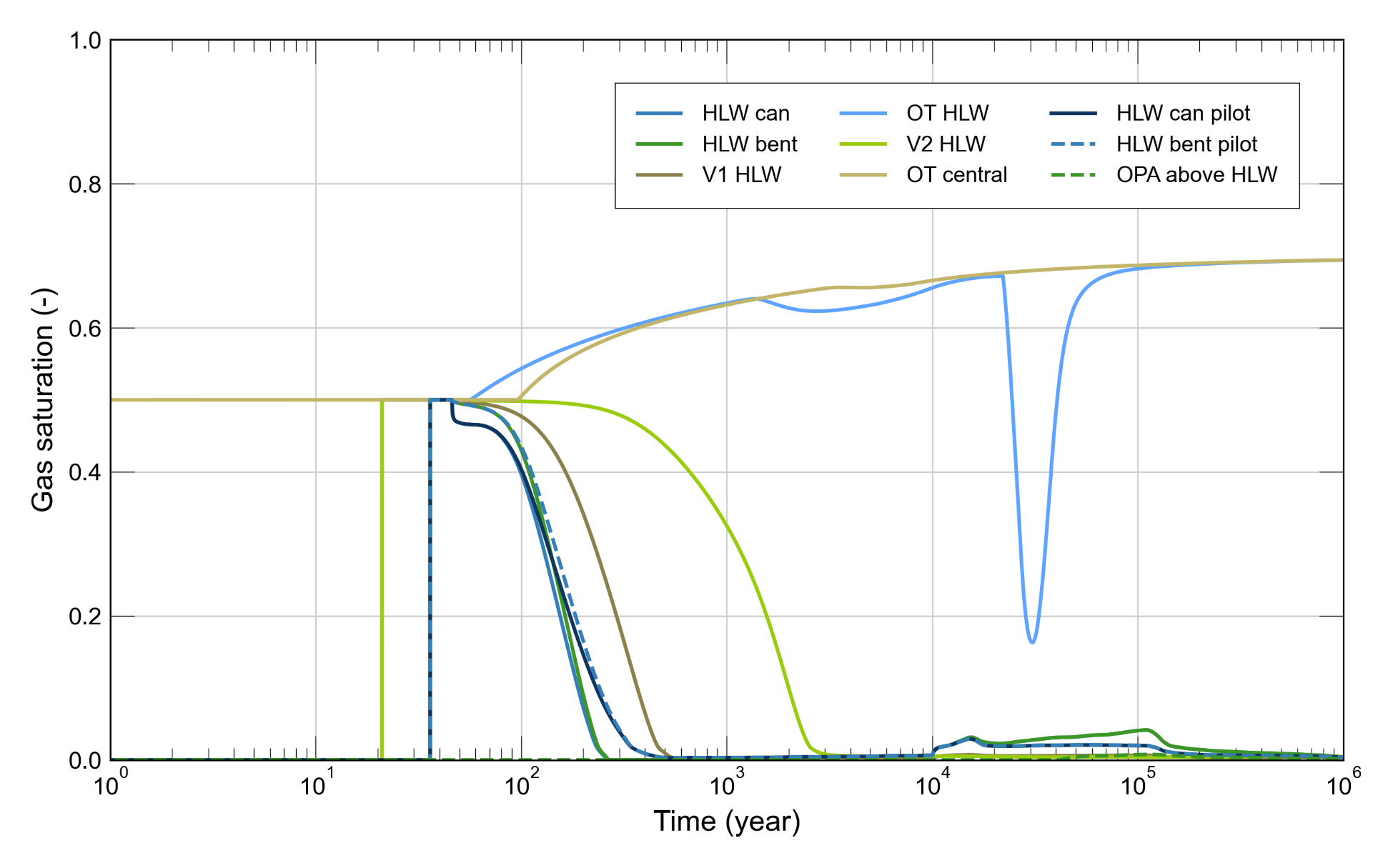
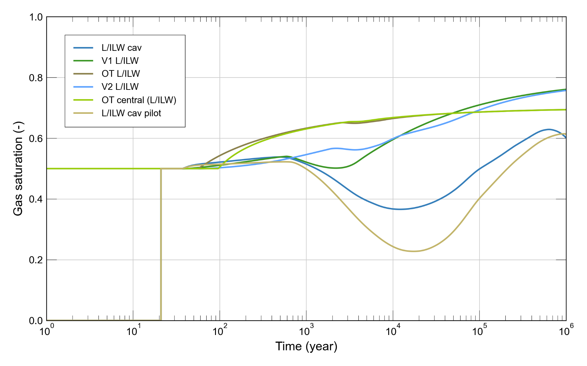
Fig. 6‑8:Assessment of total system: transients of gas saturation in the HLW repository section (top) and in the L/ILW repository section (bottom)
V1: cavern or drift seal, OT: operations tunnel, V2: repository section seal, pilot: pilot repository. For more details see Section 5.3 in Nagra 2024o.
Transient fluid pressure evolution, again from the same simulation, is shown in Fig. 6‑9. Note that pressure shown in the figure corresponds to gas pressure when a gas phase is present, and water pressure when only water is present. In the early post-closure phase (~ 1,000 years), pressure increases in the Opalinus Clay surrounding the HLW repository section due to differential thermal expansion caused by the heat emitted from the waste (Fig. 6‑10, top), reaching a peak of ~ 13 MPa after 200 years at 30 m above the centre of the HLW repository section.
By contrast, thermally induced pressures within the HLW emplacement drifts do not significantly exceed hydrostatic values. After the thermal pulse has dissipated, pressure in the HLW drifts begins to increase due to gas accumulation from the corrosion of the canisters. Upon canister breaching, assumed to occur at 10,000 years, corrosion and gas generation rates increase, and gas pressure reaches a first peak of ~ 10.5 MPa after 15,000 years, followed by a peak of ~ 11.8 MPa after ~ 115,000 years, after which gas pressure decreases towards hydrostatic since the canister has corroded away and gas generation has ceased.
In the L/ILW emplacement caverns (Fig. 6‑9, bottom), pressure starts to increase from about 36 years after emplacement due to the accumulation of waste-generated gas, reaching hydrostatic pressure after ~ 20,000 years and a peak pressure of ~ 9.3 MPa after ~ 70,000 years. Pressure in the operations tunnel and sealing sections of the L/ILW repository section follows a similar path of evolution, due to the hydraulic connection and continuous gas pathways in these repository structures. The same is observed in the pressure evolution in the central area of the repository (not shown in the figure). On the other hand, the fast restoration of hydrostatic pressure in the shaft above the V3 seal is indicative of the hydraulic separation of the shaft from the repository provided by the seal (Nagra 2024o).
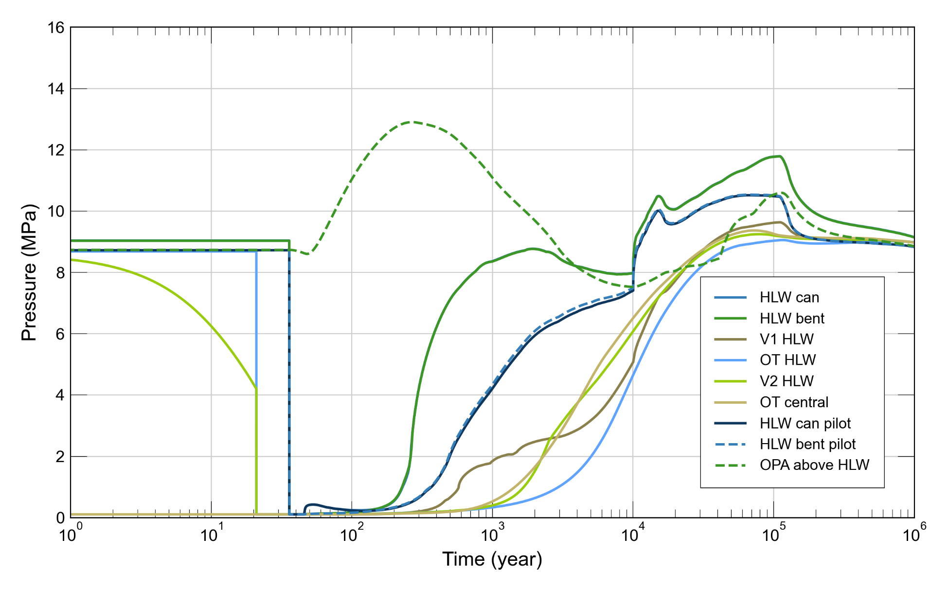
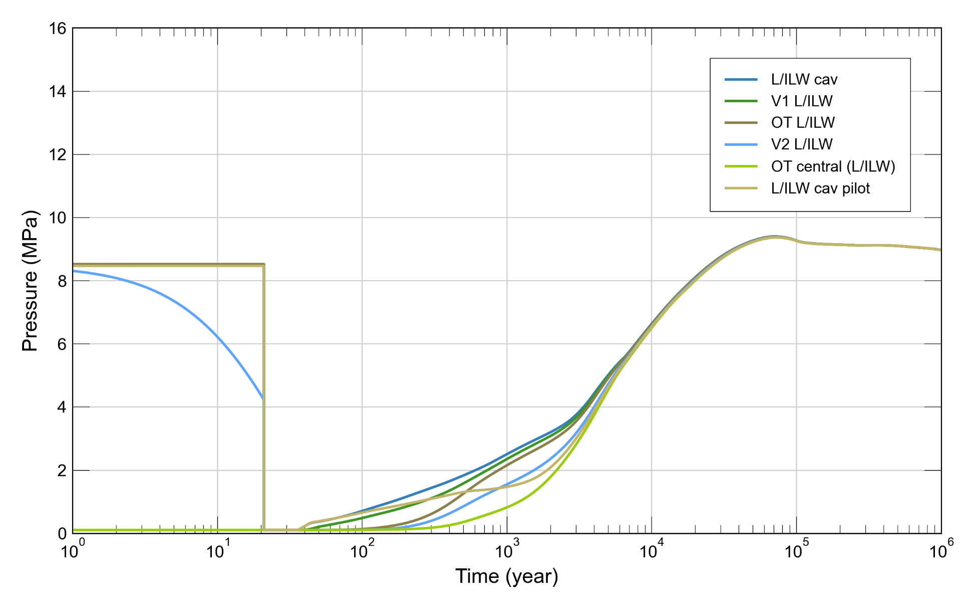
Fig. 6‑9:Assessment of total system: transients of pressure in the HLW repository section (top) and in the L/ILW repository section (bottom)
V1: cavern or drift seal, OT: operations tunnel, V2: repository section seal, pilot: pilot repository. For more details see Section 5.3 in Nagra 2024o.
The temperature drop from ~ 43 ˚C to 28 ˚C seen in the figure occurs during the ventilation period. ↩
The assessment of the production and fate of gases in the repository is presented in detail in NTB 24‑23 (Nagra 2024o) and is summarised in Section 4.3 of NTB 24‑22 Rev. 1 (Nagra 2024u) and in the following paragraphs.
The assessment of gas pressure build-up consists of a description and quantification of (1) the potential gas sources, which include the waste, barrier components such as disposal canisters and other gas-generating repository components, (2) the processes leading to gas generation, including reactions related to the corrosion of metals and degradation of organics, and (3) gas transport mechanisms shaping the hydraulic evolution of the repository described in the previous section.
The evolution of the gas generation rate and of the cumulative volume of generated gas during the time period for assessment is calculated using a range of alternative assumptions and parameter values in a set of assessment cases that account for uncertainties (deviation in performance) (see Chapters 5, 6, 7 and 8 in NAB 24‑25, Nagra 2024k for more details). The assessment cases correspond to “PA scenarios” related to the production of gas, the properties of the closure system and backfill, and the barrier function of the host rock (PA scenarios are discussed further in Section 6.4). These cases are additionally supported by probabilistic simulations to account for parametric uncertainty, as discussed in Section 6.3. The outcome of these calculations is used as input to the modelling of gas transport and the resulting build-up of pressure and associated fluid flows in the repository and surrounding rock, which are used as performance indicators.
The main outcome of the gas synthesis in Chapter 6 in NTB 24‑23 (Nagra 2024o) is a consistent hydraulic evolution of the repository adhering to the same principles and transport regimes for all calculations variants. This is the foundation for performance assessment of gas-induced effects, elaborated in NTB 24‑22 Rev. 1 (Nagra 2024u), which demonstrates that gas production in the geological repository for both HLW and L/ILW does not compromise the post-closure safety functions of either the host rock or the engineered barriers. In all the cases explored, there is a safety margin with regards to the defined performance targets. Even under the most pessimistic assumptions, the safety functions of the repository system are not degraded.
A significant observation concerns the self-regulating nature of gas pressure in the repository: an increase in the amount of gas in the pores results in a higher effective permeability for gas, which increases gas transport along the repository structures and decreases pressure build-up. The performance assessment shows that partially saturated conditions will sustain gas pathways through the repository structures such that overpressures are mitigated. This is particularly relevant to the L/ILW repository section, where gas migrates axially along the tunnels. It is shown that fully water-saturated conditions, which could result in a loss of porosity and gas permeability due to potential interactions between materials and consequently lead to gas-induced overpressures, can be excluded. By contrast, the HLW near field saturates with water within few hundreds of years, due to the high suction and thermal gradient. In all cases the saturated granular bentonite material limits the gas flow away from the corroding canisters. However, due to the low corrosion rate of the carbon steel canister under repository conditions, gas pressure build-up in the HLW drifts is not significant unless extremely conservative assumptions are made.
Another important insight from the results described in Chapter 6 of NTB 24‑23 (Nagra 2024o) is that the V3 shaft seal saturates faster than it takes for waste-generated gas to reach the shaft. This leads to gas accumulation beneath the shaft, with gradual dissipation of gas through dissolution and diffusion. Over the course of tens of thousands of years, some of this gas eventually permeates to the Malm aquifer above the repository. By then, however, gaseous radionuclide-bearing species, notably methane incorporating 14C, will have decayed within the repository system, such that there are no significant radiological consequences (see Chapter 8). The reasons for the fast saturation of the V3 shaft seals are the abundance of water from aquifers above the Opalinus Clay and the high capillary suction of the compacted bentonite material of the sealing elements.
PA modelling makes use of conservative assumptions and simplifications. For example, the corrosion and degradation of materials are conservatively decoupled from the availability of water for these reactions. In reality, gas generation ceases in dry conditions, or at low relative humidity, as water availability is the most important limiting factor for all processes that generate gas (principally the degradation of organics and corrosion of metals). As a further example, it is conservatively assumed that gas generation from the L/ILW repository section starts immediately after waste emplacement, despite the highly alkaline near-field conditions, which, in reality, are expected to decrease corrosion and inhibit microbial activity. The calculated build-up of gas overpressure could be further reduced by including in the calculations the expected thriving gas-consuming microorganisms, which are not currently accounted for, and actual gas pressure build-up could, if it were to prove necessary, be reduced by further tailoring the closure system.
The effects of parameter uncertainty on performance indicators are analysed probabilistically to identify any possible combinations of parameters that could give rise to a TH evolution of the repository that could damage or degrade the performance of the barriers and perturb the repository safety functions.
Fig. 6‑10 outlines, as an example, a probabilistic workflow with the temperature in the bentonite buffer (TB) as a performance indicator, calculated from simulations of the temperature distribution in the HLW near field. The buffer temperature is of concern, because, if it is too high, the possibility of thermally induced geochemical alteration cannot be excluded, which could alter key buffer properties, such as its swelling capacity and plasticity. Thermally induced geochemical alteration of the buffer is referred to as a deviation in performance, which, if it cannot be excluded, is propagated to safety scenario development and to the analysis of radiological consequences.
The workflow starts with the definition of uncertainty ranges for thermal and hydraulic parameters as explained in detail in Chapter 3 of NAB 24‑25 (Nagra 2024k). Representative parameter values from these ranges are selected as a reference case. In addition, 100 Latin Hypercube samples are taken for the probabilistic realisations. TH-simulations of the HLW near field are carried out for a model domain consisting of a 2D vertical cross-section through the repository centre (Fig. 6‑10 central figure). Transients of the performance indicator TB are monitored at a control point in the bentonite buffer, 7.5 cm above the canister. For each simulation, the maximum temperature, TB,max, is calculated and is normalised by dividing by the performance target of Tmax = 150°C, yielding a dimensionless performance index, denoted by NBT. The performance target represents the maximum temperature in dry bentonite that can be maintained without causing irreversible geochemical alterations. A histogram showing both a probability density function (PDF) and cumulative density function (CDF) of NBT aids in calculating whether Tmax could be exceeded. Additional details on the workflow are given in NTB 24‑22 Rev. 1 (Nagra 2024u).
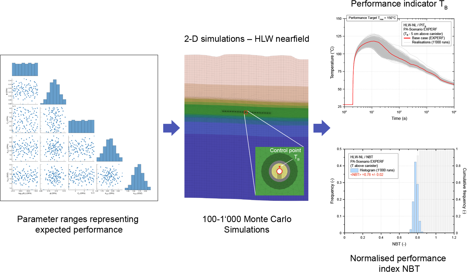
Fig. 6‑10:Probabilistic workflow for the simulation of the temperature distribution in the HLW near field, with the bentonite temperature (TB) as a performance indicator
Scatter-plot matrix of the 100 Latin Hypercube samples from distributions of thermal and hydraulic input parameters (left); Close-up of the 2D model through the centre of an HLW emplacement drift, with the control point representing the performance indicator TB in the bentonite buffer (centre); Transients of the performance indicator TB comprising the reference case and 100 probabilistic realisations, representing the uncertainty range of the performance indicator (right above). Finally, histograms with probability density function and cumulative density function of NBT (right below) aid in calculating performance margins and evaluation scales (see Nagra 2024k for further details).
The results show that, in this example, the performance target is met with a wide safety margin. The same is true for other performance indicators considered in the PA (Nagra 2024u), indicating that, over a wide range of conditions spanning all identified parameter uncertainties, the integrity of the barriers will be maintained, and the system is expected to perform its safety functions as designed.
The assessments described in the previous sections involve the use of multiple PA models and, in some instances, chains of models. The appropriateness of a model depends on its subjective representation of the real-world system and its intended use. Suitability for the intended purpose can be evaluated through a well-planned Code and Calculation Verification and Model Validation (V&V) programme, considering qualitative and quantitative performance measures.
In the probabilistic workflow described previously, uncertainty in the ranges of input parameters is propagated directly to uncertainty in model output and potentially further (e.g., if parameter uncertainty results in situations where a performance target may not be met) to the development of safety scenarios and to the analysis of radiological consequences. Uncertainty is, however, also associated with model abstraction, or conceptualisation, which inherently introduces inaccuracy and additional uncertainty by simplifying real-world systems. Assessing such uncertainties within the PA workflow is integral to building confidence in the evaluation of post-closure performance and safety for the deep geological repository.
Chapter 5 of NTB 24‑22 Rev. 1 (Nagra 2024u) provides a detailed discussion of model abstraction in the context of PA, including:
-
geometric abstractions,
-
the simplified representation of phenomena and processes, and
-
homogenisation and the scaling of parameters.
Nagra’s efforts in code-benchmarking and PA model validation are detailed in Section 5.7 of NTB 24‑22 Rev. 1 (Nagra 2024u). In general, it is shown that the impact of abstractions is either small or errors on the side of conservatism; see, however, the discussion of the characterisation of the geological barrier below.
Section 6.2 above presents an analysis related to the thermally-induced geochemical alteration of the buffer as an example of a deviation in performance, the potential for which are explored by modelling. Such deviations in performance could potentially arise in certain “PA scenarios”, e.g., upper bound heat production in the HLW canisters. A wide range of PA scenarios is considered, primarily through modelling, including the expected performance of the repository, which is also categorised as a PA scenario.
The results from performance assessment (for details see NTB 24‑22 Rev. 1, Nagra 2024u) indicate that most PA scenarios do not affect the broad descriptions of the evolution of the pillars of safety in any substantive way, i.e., performance targets are met even for combinations of unfavourable parameters explored using the probabilistic workflow, generally with a large safety margin, as illustrated by the example in Fig. 6‑10. This shows that the repository system is highly robust regarding uncertainties related to the repository system performance and that the repository is likely to evolve according to its “expected performance” as described e.g., in NAB 24‑20 Rev. 1 (Nagra 2024m). PA scenarios that result in only minor deviations in performance are propagated, along with the PA scenario for expected performance, to the “reference safety scenario” and its variants, described further in Section 7.2.
There are several PA scenarios that relate to the properties of the CRZ. Compared to the engineered barriers, which are assumed to adhere to their design specifications, certain aspects of the CRZ involve some uncertainty. As noted in Section 6.2.1, PA modelling generally assumes that diffusion is the dominant transport mechanism in the CRZ, and that advection along steeply dipping faults does not represent a relevant transport mechanism. Furthermore, it is assumed that sedimentary features, such as hard beds in the upper and lower confining geological units, do not act as lateral release paths. While these assumptions are well supported, some uncertainty remains due to inevitable incompleteness in geological characterisation. Thus, there are PA scenarios that assume the unlikely presence of an undetected, water-conducting fault, or the presence of water-conducting sedimentary features within the confining geological units, which cannot be excluded a-priori, even in the repository construction phase. If they were to occur, such features could affect (at least locally) the conceptualisation of radionuclide transport in the geosphere as a diffusion-dominated process. These PA scenarios are propagated to alternative safety scenarios, as described in Section 7.3, or, if extreme and hypothetical properties for such features are assumed, to the “what-if” cases described in Section 7.4.
Finally, some PA scenarios, such as the creation of new faults, or the re-activation of existing faults, in the post-closure period by repository-induced effects, i.e., by the effects of repository heat and repository-generated gas, or by geological phenomena such as earthquakes, have been shown in the PA in NTB 24‑22 Rev. 1 (Nagra 2024u) and in the assessment of earthquake scenarios in NAB 24‑28 (Nagra 2024g) to be either implausible or exceedingly unlikely. It has also been shown that the excavation of the repository by erosion, within a million-year time frame, by erosive processes is hypothetical. These effects are, nonetheless, considered in the “what-if?” cases in safety scenario development, as described in Section 7.4.
Future human actions (FHA) and their potential radiological consequences do not fall within the scope of PA. Rather, these are considered separately, as reported in NAB 24-09 (Nagra 2024r). FHA safety scenarios are described in Section 7.5.