
5. Assessment basis (NTB 24-10)
Aims of the chapter:
- To describe the assessment basis, which has been developed over decades and allows for a comprehensive assessment of performance and safety.
- To describe the geological setting and the containment-providing rock zone in which the repository is located.
- To describe the initial state of the repository system and provide a short summary of its expected evolution and the fate of radionuclides.
Confidence in the findings of safety assessment requires a sound scientific understanding of the repository system and its evolution and that uncertainties are identified and, where possible, quantified. Nagra’s scientific understanding relevant to the post-closure safety of the proposed repository system and its associated uncertainties has been developed through an interdisciplinary and collaborative programme of RD&D and site characterisation. Understanding of the long-term behaviour of the repository system and its geological setting is supported by wide ranging information, including:
field observations and monitoring activities,
laboratory experiments, field testing and demonstration/verification activities,
modelling studies,
literature surveys, and
expert elicitation.
The following paragraphs summarise the assessment basis relevant to the safety assessment of a geological repository for both HLW and L/ILW. A detailed description, including references to data sources, can be found in the referenced reports.
The current integrated understanding of the geology of Northern Switzerland, encompassing the siting regions considered in Stage 3 of the Sectoral Plan, is provided in the Geosynthesis of Northern Switzerland in NTB 24‑17 (Nagra 2024i), and includes information on:
-
the overall geological setting,
-
past geological evolution,
-
the properties of relevant geological elements, including the CRZ, and
-
the expected long-term geological evolution in the future.
The following summary is a short excerpt of the broader information presented in NTB 24‑17 (Nagra 2024i) and supporting materials.
Key geological properties (datasets) that led to the selection of the site are summarised in Fig. 5‑1. The site lies in a tectonically quiet and stable area with limited deformation in the external northern Alpine foreland basin (Section 1.5 of NTB 24‑17, Nagra 2024i). It is located away from large-scale tectonic zones of increased geological complexity (Alps, Internal Jura, Upper Rhine Graben, Hegau – Bodensee Graben). The area is characterised by low seismic activity and low deformation and uplift rates. In the potential repository zone, the host rock (Opalinus Clay) occurs ~ 900 m below ground level in a flat-lying configuration with a thickness of around 105 m (Section 4.2.6 of NTB 24-17, Nagra 2024i). 3D seismic data indicate that the potential repository zone is in an area devoid of any seismically mappable faults (Section 4.3.4 of NTB 24-17, Nagra 2024i). Past deformation has essentially been accommodated in regional faults zones situated to the north and to the south. The same is also expected for tectonic deformation that could potentially occur during the time period for assessment (Section 6.6.2 in NTB 24-17, Nagra 2024i). The regional geological setting and the local host rock configuration thus provide stable geological conditions regarding long-term geological changes of the site. The size of the area without mappable signs of tectonic faults ensures flexibility with respect to the repository design.
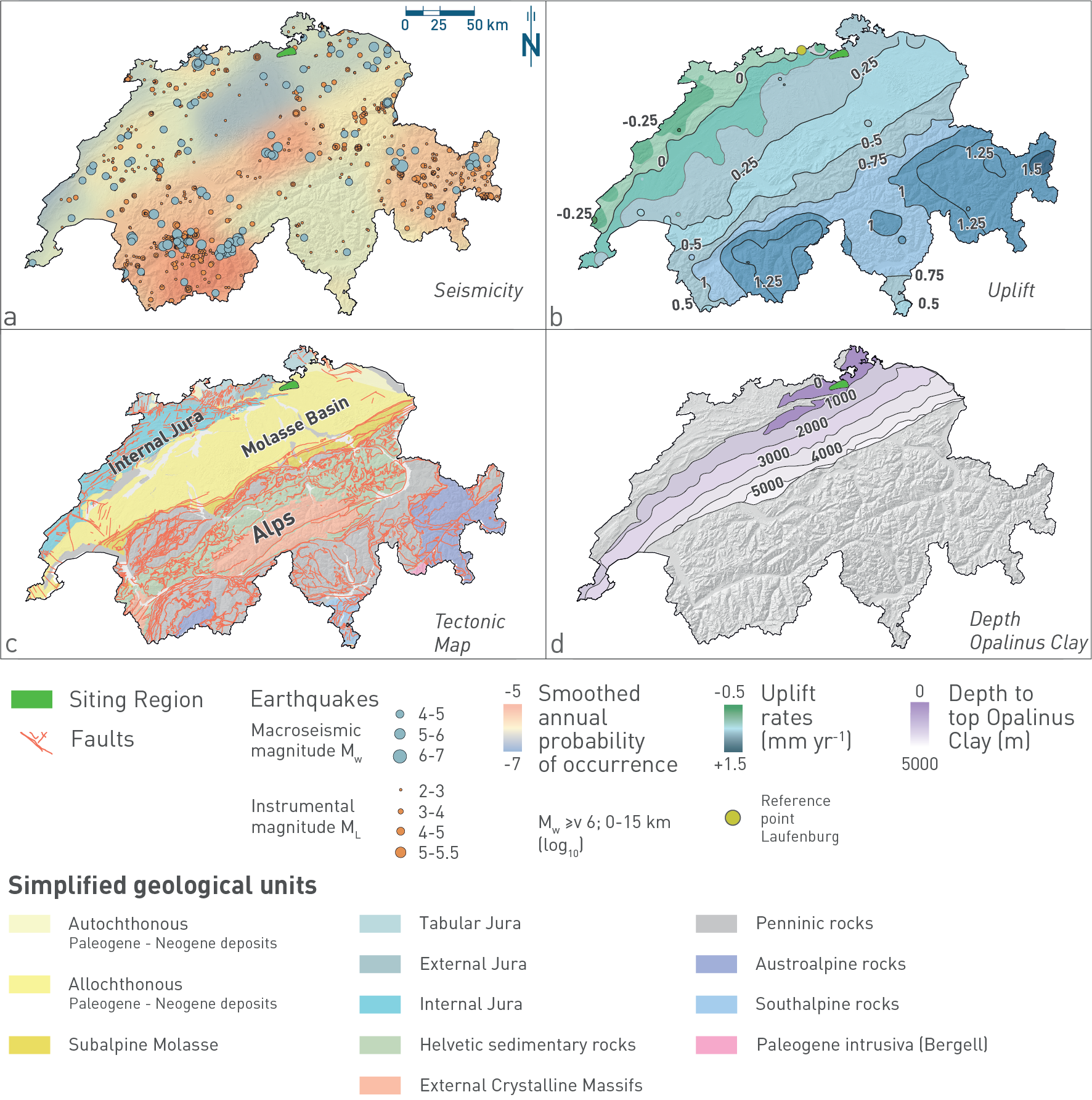
Fig. 5‑1:Key datasets used for selecting the site in Northern Switzerland
The site is characterised by low (a) seismic activity and (b) uplift rates. 3D seismic data indicate that the repository will be located in an area (c) devoid of any seismically mappable faults and (d) where the Opalinus Clay occurs ~ 900 m below ground level in a flat-lying configuration with a thickness of around 105 m.
Simplified from Fig. 1-3 in Chapter 1 of NTB 24-17 (Nagra 2024i).
The host rock, Opalinus Clay, consists of a ca. 174 Ma old, ca. 105 m thick and clay-mineral rich unit with very low hydraulic conductivity (Fig. 5‑2), embedded in low-permeability confining geological units (Section 4.2.6 and Chapter 5 in NTB 24-17, Nagra 2024i).
The aquitard sequence comprising the host rock and its low-permeability confining geological units, which is at least 300 m thick, is overlain by the regional Malm aquifer (Section 4.5.3 in NTB 24-17, Nagra 2024i). The ca. 40 m thick, clay-mineral-poor «Herrenwis Unit» is regarded as part of the low-permeability upper confining geological units, as the observed hydraulic conductivities are low, and the whole unit is embedded in clay-mineral-rich sequences. Observed low hydraulic heads indicate that the «Herrenwis Unit» is hydraulically isolated from the regional flow systems.
The Malm aquifer overlying the thick aquitard sequence is characterised by a fracture-dominated permeability, which mainly occurs in the upper part of the unit. Groundwater in the Malm aquifer contains a fossil marine component indicating rather stagnant flow conditions. This is confirmed, e.g., by compositions of stable isotopes of groundwater as illustrated in Fig. 5‑2 (Section 4.5.5 in NTB 24-17, Nagra 2024i)
The first potential aquifer below the aquitard sequence is the Keuper aquifer (Section 4.5.3 in NTB 24-17, Nagra 2024i) Regionally, this is a complex aquifer with potential water-conducting zones in different subunits. Next to the site, zones with increased hydraulic conductivities have only been observed in conjunction with localised fluvial deposits with increased porosity in two boreholes in the western part of the region (in the BAC1-1 and STA2-1 boreholes). The sampled groundwater is a mix of meteoric and higher saline water components (Section 4.5.5 in NTB 24-17, Nagra 2024i) As the transmissive fluvial deposits occur only locally, the Keuper aquifer is not regarded as an effective flow system and the underlying units can contribute at least locally to the transport barrier (Section 4.9 in NTB 24-17, Nagra 2024i) Due to the heterogeneous nature of water-conducting units, the uncertainty regarding the significance of the Keuper aquifer for advective transport remains comparably large.
The next aquifer of regional hydrogeological importance below the host rock is the Muschelkalk aquifer, a fractured aquifer including zones with increased porosity (see Section 4.5.3 in NTB 24-17, Nagra 2024i) The Muschelkalk aquifer hosts the most dynamic deep aquifer at the site. The groundwater is of cold-time meteoric origin (Section 4.5.5 in NTB 24-17, Nagra 2024i)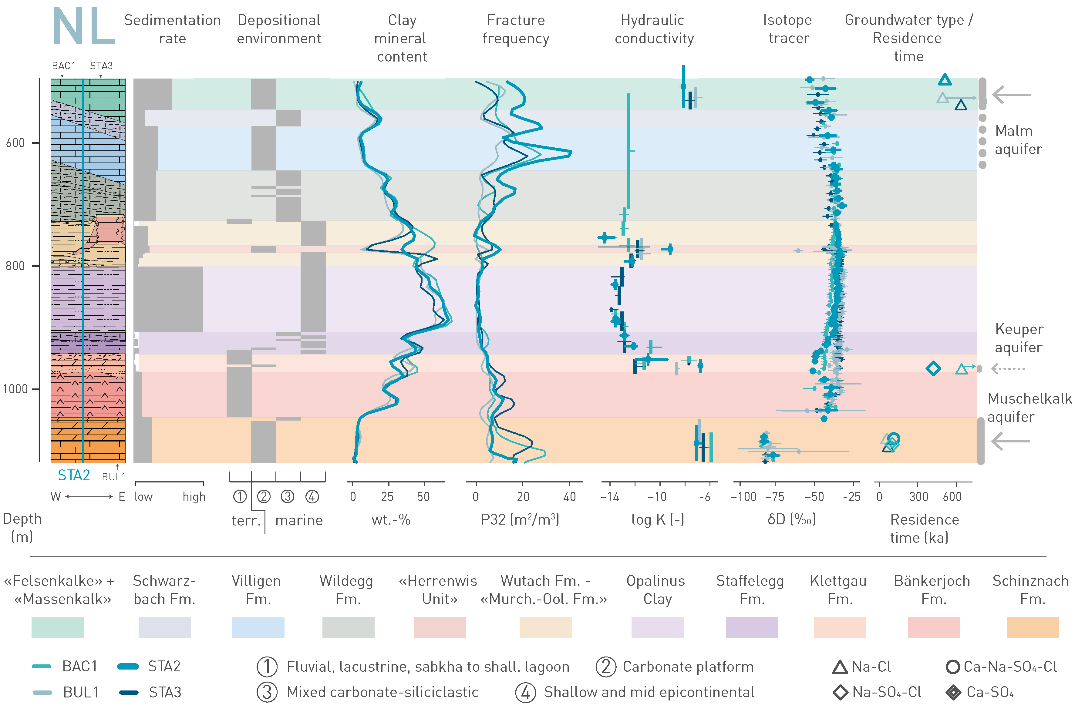
Fig. 5‑2:Synthesis of key observations of the rock sequence between the Muschelkalk and Malm aquifers at the site
Data from three deep boreholes, labelled BAC-1, BUL-1 and STA-3, are projected to the data of the reference borehole labelled STA-2. For further explanation of this figure, consult Section 4.9 in NTB 24-17 (Nagra 2024i). The figure shows that the low-permeability zone around the host rock is delimited in the vertical direction by the occurrence of aquifers. The profiles of the natural tracers in between the aquifers can be explained by diffusive transport. The regional Malm and Muschelkalk aquifers define the maximum extent of the low-permeability zone. In between, the locally occurring Keuper aquifer must also be considered.
The hydraulic head distribution within the CRZ is controlled by the difference of hydraulic heads and distribution of conductivities between aquifers above and below the Opalinus Clay. Hydraulic head measurements in the regional aquifer systems were carried out in deep boreholes. The hydraulic head was regionally assessed using a hydrogeological model (Section 4.5.4 in NTB 24-17, Nagra 2024i). By considering the distance between aquifers and the vertical distribution of hydraulic conductivities in the aquitards, the magnitude and direction of the vertical hydraulic gradient could be determined. As stated above, the Malm aquifer is the closest above the Opalinus Clay, with the Muschelkalk aquifer below and the Keuper aquifer potentially reducing the distance between aquifers.
Hydraulic head differences are small within the site. While the combination of the Malm and Muschelkalk aquifers shows overall downward gradients, the northern part of the site indicates weak upward gradients when the Keuper aquifer is considered.
The absolute magnitude of the hydraulic head difference is mainly below ca. 100 m within the site.
The host rock is characterised by a fine and homogeneous pore structures, a very low hydraulic conductivity and, consequently, diffusion-dominated solute transport and a high self-sealing capacity (Chapter 5 in NTB 24-17, Nagra 2024i). It has a homogeneous and high clay-mineral content giving it a high sorption capacity for many radionuclides. Moreover, the mineralogy allows for efficient porewater buffering, providing stable and reducing geochemical conditions. Its exceptionally low lateral and horizontal variability is due to a relatively uniform marine depositional environment characterised by high clay-mineral input and relatively high sedimentation rates (Section 3.3.2 of NTB 24-17, Nagra 2024i).
Any so-far undetected subseismic faults are not expected to represent distinct flow paths. This is primarily due to deformation in the Opalinus Clay, which is typically accommodated in a distributed manner with soft-linked segmented fault planes, making continuous flow paths unlikely (Section 5.10 in NTB 24-17, Nagra 2024i). Secondly, the low stiffness and the high swelling capacity of the clay-mineral-rich host rock results in efficient self-sealing of fractures. A clear relationship between high clay-mineral content and low hydraulic conductivity was confirmed by the analyses of numerous hydraulic packer tests carried out during the most recent field investigations (Fig. 5‑3).
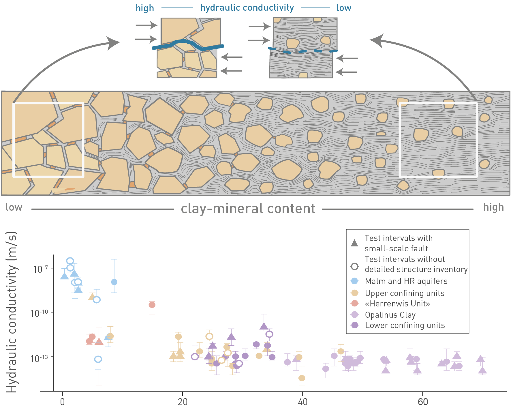
Fig. 5‑3:Link between texture and clay-mineral content and the hydraulic properties in Mesozoic sediments of Northern Switzerland (lower confining units to upper aquifers)
Note Opalinus Clay values with consistently high clay contents and very low hydraulic conductivities.
The uppermost figure depicts a highly simplified transition from a grain-supported framework (clastics or carbonate skeleton, with low clay-mineral content partially filling the pores) on the left side, to a clay-matrix-supported framework on the right. Transition to the clay-matrix-supported framework at approximately 20 to 40 wt.-% is consistent with the low hydraulic conductivities. Note: figure shows data from Liassic to Malm. For further explanation of this figure, consult Section 5.10 in NTB 24-17 (Nagra 2024i).
Independent evidence for the highly effective barrier function of the host rock and confining geological units over geological timescales and for diffusion-dominated transport is provided by natural tracer profiles of the porewater composition (see Section 9.1.1).
Long-term geological evolution has been described in Chapter 6 of NTB 24-17 (Nagra 2024i) and in the references therein. A short excerpt is given in the following paragraphs to contextualise the results from the perspective of safety assessment.
Recent tectonic deformation rates in Northern Switzerland are small compared with those in the geological past. The study of past geological evolution shows that deformation is preferentially accommodated by larger existing faults, which represent zones of weakness. Future deformation will thus most likely result in fault reactivation of existing faults. These are avoided when placing the disposal areas. If new faults were to develop cutting through the host rock, they are expected to be segmented and small in length and offset.
Future erosive processes (glacial and non-glacial) are expected to be comparable with those that occurred in the Quaternary period, but the rates are likely to be lower (no major drainage reorganisation, smaller glaciers, delay in glacial inception, and harder-to-erode rocks). Due to the great emplacement depth, the repository system is protected against future erosion. Excavation of the repository by either glacial or non-glacial (fluviatile) erosion processes within the next million years is not expected. Furthermore, a residual cover of at least 200 m, which ensures the self-sealing capacity of the host rock, is expected to remain present throughout the time period for assessment of one million years.
Climate change, glaciations, permafrost, and erosion can affect aquifer dynamics, including a shortening of the transport path along aquifers and the possibility of increased flow rates. Glacial loading may lead to overpressures in the host rock and to a temporarily increased hydraulic gradient and transport rates from the host rock towards the aquifers. However, mass transport is expected to remain diffusion dominated. Because of the buffering capacity of the host rock minerals, geochemical conditions will remain reducing.
A narrative of the initial state and expected evolution of the repository system is presented in the following sections. It is based on sound scientific understanding and accounts for uncertainty, as documented in the assessment basis reports (Fig. 1‑1), and as brought together in more detail in NAB 24‑20 Rev. 1 (Nagra 2024m). Arguments and evidence supporting key claims within this account of the expected evolution are validated by the performance assessment (PA), as summarised in Chapter 6.
In Switzerland, the largest producers of radioactive waste are the nuclear power plants (NPPs). Other sources are applications in medicine, industry and research. All waste emplaced in the repository will be required to conform with waste acceptance criteria. The corresponding radionuclide inventory, the waste packages, masses, and volumes are included in the MIRAM (Model Inventory of Radioactive Materials) database for the general licence application (Nagra 2023b).
Five types of waste will be disposed of in the HLW repository section: two types of RP-HLW and three types of SF. RP-HLW contains most of the fission products from the spent fuel assemblies reprocessed at La Hague, France and at Sellafield, United Kingdom. During the production of this reprocessed waste, the liquid glass is poured into cylindrical steel moulds, which are then sealed. After cooling, the glass forms a homogeneous waste matrix. Spent fuel (SF) consists of fuel assemblies removed from Swiss NPPs and, to much lesser extent, from research reactors. The numbers of canisters for each waste type are presented in Tab. 5‑1.
Tab. 5‑1:HLW types and the numbers of canisters for each type
|
HLW type |
Number of canisters |
|
Boiling water reactor SF |
891 |
|
Pressurised water reactor SF without MOX |
694 |
|
SF from the PSI Hot Laboratory and from the PSI-Diorit II Reactor* |
5 |
|
Pressurised water reactor SF including MOX |
345 |
|
RP-HLW from La Hague |
145 |
|
RP-HLW from Sellafield |
65 |
* Considered together with the pressurised water reactor SF without MOX in the analysis of radiological consequences.
Alpha-toxic waste (ATW) and low- and intermediate-level waste are disposed of in the L/ILW repository section. Both cover a broad spectrum of radioactive waste. ATW comprises (see Tab. 5‑2):
-
waste from the reprocessing of spent fuel assemblies (structural parts of reprocessed fuel assemblies and waste from the operation of reprocessing plants), and
-
operational waste from research facilities, especially PSI and CERN, and various wastes from medicine and industry.
L/ILW (see Tab. 5‑2) comprises:
-
operational waste from the NPPs (resins, concentrates, sludges, mixed waste), the ZWILAG interim storage facility and the encapsulation plants for the deep geological repository,
-
reactor waste from NPPs (mainly activated, replaceable reactor components),
-
decommissioning waste from the NPPs (activated and contaminated reactor and building components and secondary waste arising during conditioning of the decommissioning waste), the interim storage facility and the encapsulation plants for the deep geological repository, and
-
operational and decommissioning waste from research facilities, in particular PSI and CERN, and various wastes from medicine and industry.
ATW and L/ILW both consist of metallic, organic and inorganic materials, which are generally conditioned prior to interim storage.
Tab. 5‑2:L/ILW types and the numbers of waste packages for each type
|
Origin of waste |
KEV |
Number of waste packages |
|
Operational |
L/ILW |
51,020 |
|
Reactor |
L/ILW |
1,121 |
|
Decommissioning |
L/ILW |
12,475 |
|
Reprocessing |
L/ILW |
0 |
|
Operational |
ATW |
1,702 |
|
Reactor |
ATW |
0 |
|
Decommissioning |
ATW |
4 |
|
Reprocessing |
ATW |
552 |
The repository is constructed around 900 m below ground, in the middle of the Opalinus Clay host rock layer, with separate repository sections for the emplacement of SF and RP-HLW (the HLW repository section) and for L/ILW and ATW (the L/ILW repository section). Regional tectonic elements and seismically mappable faults are avoided with a sufficient respect distance, which is determined by performance assessment, see Section 3.7.2 in NTB 24-22 Rev. 1 (Nagra 2024u).
The following description refers to the current repository design. Future adaptions and optimisation to simplify and optimise the repository implementation will be carried out in full compliance with the regulatory requirements.
The construction of all underground structures is carried out in compliance with all relevant requirements and specifications. A respect distance to the exploratory boreholes is also observed (50 m from the disposal areas, Section 4.1.5 in NAB 24-18 Rev. 1, Nagra 2024s).
If necessary, measures are undertaken to ensure that any deviations from the planned implementtation occurring in the pre-closure period have no impact on post-closure safety.
The HLW emplacement drifts are continuously backfilled with a bentonite buffer immediately after emplacement of the individual disposal canisters. As soon as an emplacement drift has been filled entirely, it is closed with a V1-HLW seal. The emplacement caverns for L/ILW and ATW are divided into compartments. Each compartment is backfilled with cementitious mortar within a few days after emplacement of the disposal containers. After all compartments in a cavern have been filled, the cavern is closed with a V1-L/ILW seal (Fig. 3‑9).
The period of repository monitoring starts once all waste has been emplaced, as described in the Waste Management Programme 2021 (Nagra 2021c). Early in this phase, the accesses to the HLW and L/ILW repository sections are backfilled and sealed at the repository level with V2 seals. At the end of the monitoring period, test areas and all other underground structures that are still open are backfilled, and the access structures are sealed with V3 seals. The closure of the repository is again carried out with state-of-the-art technologies and best engineering practices and is assumed to comply with all relevant requirements and specifications.
The excavation, cooling, and ventilation of the underground openings results in the gradual desaturation and depressurisation of the surrounding rock, which eventually resaturates when ventilation ceases. Transient processes associated with ventilation include:
-
drying out of tunnel support materials,
-
creation of desiccation cracks in the surrounding rock,
-
precipitation of salts in these cracks due to evaporation of porewater,
-
an increase in salinity of the porewater, and
-
carbonation of cementitious materials, due to reaction with CO2 in the air.
An Excavation Damaged Zone (EDZ) also forms around the underground openings. The EDZ, however, reseals in the post-closure period as it resaturates (see Chapters 3 and 4 in NAB 24-20 Rev. 1, Nagra 2024m).
After closure, the V3 seals that are placed in the access shafts to seal the repository from the surface environment saturate relatively rapidly, due to their high suction and the flow from more permeable rock formations above down the shafts and into the seals. Once saturated, the sealing elements have a low permeability to both water and gas (permeability to water of 10-19 to 10-18 m2). This largely prevents further water flow down the shafts into the as yet unsaturated underground structures of the repository. It also largely prevents the migration of repository-generated gas from the underground structures of the repository towards the surface environment (see the discussion of the fate of repository-generated gas in Section 6.2.3). This is relevant to radiological safety, as repository-generated gas can transport 14C, mainly in the form of methane (14CH4).
After the emplacement of L/ILW and ATW and the backfilling and sealing of the emplacement caverns, the partially saturated EDZ and rock support around the L/ILW caverns largely resaturate with water and the EDZ fractures re-seal, although some gas-filled pores can remain as a result of repository-generated gas (see below). Some water can also enter the caverns and accumulate under gravity at the cavern floor. Anaerobic and reducing conditions develop due to the consumption of O2 in trapped air and hyperalkaline conditions develop in the porewater within and around the caverns due to the presence of cementitious materials (see Chapter 6 in NAB 24-20 Rev. 1, Nagra 2024m).
Gas generation takes place due to corrosion of metals and degradation of organic materials in the caverns. Some of this gas dissolves in porewater within and around the caverns, with the remainder accumulating within the caverns, increasing the gas pressure and limiting further inflow of water. The V1-L/ILW seals that close the L/ILW caverns and the V2 seals that isolate the L/ILW repository section from the rest of the deep geological repository also start to saturate, but full saturation is prevented by the gas pressure in the caverns. The gas migrates through the seals and accumulates in the backfill of the adjoining underground structures, providing a storage volume for the gas in addition to that provided by the caverns themselves. Desaturated conditions persist in the upper parts of the L/ILW emplacement caverns and in the backfill of the connected underground structures for several tens of thousands to hundreds of thousands of years, until gas generation ceases. Some gas may enter the host rock but will migrate through it without causing damage. Pore clogging due to cement – clay interactions within the V1-L/ILW and V2-L/ILW seals that might impact overall seal permeability is not expected, as explained in Section 6.5 of NAB 23-21 (Martin et al. 2023), eespecially given that it is likely that the seals remain only partially saturated for the entire period of gas production (Section 7.2.4 in NAB 23-21, Martin et al. 2023).
Transient heat initially produced by cement hydration and, in the longer term, radiogenic heat from the L/ILW, and especially from ATW, leads to a transient short-term increase in temperature within and around the L/ILW disposal area. This heat, in combination with gas penetration, also leads to elevated pore pressures. These elevated temperatures and pore pressures, however, are small and have no long-term impact on the performance of the barriers (Appendix A.5 in NAB 24-20 Rev. 1, Nagra 2024m).
The disposal containers provide an initial resistance to water ingress, but they degrade over time, and, after a few hundred years, water encounters the waste matrices in at least some of the containers, and the radionuclides embedded within them start to be dissolved. 14C, mainly in the form of methane (14CH4), may also mix with the repository-generated gas in the emplacement caverns and closure system.
The tunnel support system around the emplacement caverns degrades and loses its mechanical strength over time, but the resulting stress redistribution has no impact on the safety-relevant properties of the barriers. In particular, the presence of backfill material limits cavern convergence to the extent that no previously sealed EDZ fractures are reactivated (Geomechanica Inc. 2025).
The cementitious near field evolves over time due to the mineralogical evolution of cement phases. A high pH is expected to be maintained for at least 100,000 years (Section 3.3.5 in NTB 23-03, Kosakowski et al. 2023). Interactions between the cementitious near field and the surrounding rock are of limited spatial extent and do not affect the safety-relevant properties of either barrier (Section 3.3.4 in NTB 23-03, Kosakowski et al. 2023). In particular, any pore clogging that occurs due to precipitation does not reduce the overall permeability to gas.
After emplacement of the HLW disposal canisters, as well as the buffer and V1-HLW seals in the emplacement drifts, the partially saturated EDZ and rock support around the tunnels resaturate with water, followed by saturation of the buffer and seals. EDZ fractures re-seal. The compacted clay structures (the buffer and the sealing elements of the V1-HLW seals) saturate relatively quickly due to their high capillary pressure (suction), though the rate of saturation is limited by the low permeability of the rock and impacted by decay heat generated by the waste. Full saturation is expected to occur some hundreds of years after emplacement (Chapter 7 n NAB 24-20 Rev. 1, Nagra 2024m). Saturation is sufficiently regular and any initial inhomogeneities in the buffer density are reduced over time, thus no potentially damaging stresses will be exerted on the canisters. The buffer density around the canister is sufficiently high to prevent, when saturated, microbial activity that might otherwise increase the rate of canister corrosion (Section 5.6 in NTB 19-03, Nagra 2019).
Anaerobic and reducing conditions develop due to the consumption of O2, e.g., by canister corrosion. Radiation shielding provided by the disposal canisters is sufficient to protect the barriers from radiation-induced effects. Slow gas generation takes place due to the gradual anaerobic corrosion of the disposal canisters. Much of this gas dissolves in the porewater of the saturated bentonite buffer surrounding the canisters and diffuses through the tunnel support system into the Opalinus Clay porewater. However, some gas also migrates in the gas phase through the buffer and into the rock, where it dissolves (Chapter 6 in NAB 24-20 Rev. 1, Nagra 2024m). Gas migration causes no irreversible changes to either the buffer or the rock (Section 4.4.2 in NTB 24-22 Rev. 1, Nagra 2024u).
In the first few thousands of years following repository closure, repository-generated heat, primarily decay heat from the waste packages, leads to a transient increase in temperature and pore pressure within and around the HLW disposal area, including within the CRZ (Chapter 6 in NAB 24-20 Rev. 1, Nagra 2024m). However, these elevated temperatures and pore pressures have no long-term impact on the performance of the barriers. The tunnel support system around the emplacement drifts degrades and loses its mechanical strength (Section 6.7.2 in NTB 23-02 Rev. 1, Nagra 2024v), but the resulting stress redistribution has no impact on the safety-relevant properties of the barriers (any reactivation of EDZ fractures will be temporary, as the fractures will re-seal, see Appendix A-2 in NTB 19-03, Nagra 2019).
Porewater composition in the buffer becomes anoxic and reducing, gradually equilibrating with that in the rock (Chapter 7 in NTB 23-02 Rev. 1, Nagra 2024v). Chemical interactions, including interactions between canister corrosion products (Section 8.2.3 in NTB 23-02 Rev. 1, Nagra 2024v) or the cementitious lining and the clay barriers (Section 6.7.2 in NTB 23-02 Rev. 1, Nagra 2024v), are of limited spatial extent and do not affect the safety-relevant properties of the barriers.
In the post-closure period, but after at least ten thousand years, disposal canisters become locally breached due to mechanical failure following weakening by corrosion (Section 4.3 in NTB 24-20, Nagra 2024d). The exposure of internal metal surfaces to water results in corrosion of these surfaces and locally increased gas production rates. The evolution of the waste packages following canister breaching is described in the context of radionuclide release, retention, and transport in Section 5.4.1.
Long-term geological and climatic evolution, including glacial and fluviatile erosion and uplift, geomorphological effects and activation or re-activation of fault zones due to natural processes, are not expected to negatively impact the safety-relevant properties of the barrier system over the time period for assessment of one million years. While, over a period of hundreds of thousands of years, erosion processes, in combination with uplift, gradually result in a partial loss of overburden, an exhumation of any part of the disposal areas, or any decompaction of the CRZ that would affect safety-relevant properties (especially its porosity, hydraulic conductivity, and self-sealing capacity) can be ruled out over the time period for assessment.
Understanding transport pathways for any radionuclides released from the repository is necessary to guide performance assessment, focusing on key aspects of barrier functionality and barrier evolution over time, and to evaluate potential radiological consequences. This section provides a broad-brush description of how radionuclides are expected to migrate through repository barriers. It is based on the qualitative description of the expected phenomenological evolution of the repository as presented in Chapter 9 in NAB 24‑20 Rev. 1 (Nagra 2024m).
A monitoring period starts after the completion of waste emplacement operations. After an initial period of monitoring, the disposal area accessways will be backfilled and sealed. This is followed by a second monitoring period that is currently assumed to last several decades (as e.g., described in the Waste Management Programme (Nagra 2021c). After this monitoring period, the whole repository is closed13 and the post-closure period begins. Evolution in the post-closure period with respect to the fate of radionuclides can be described in terms of five periods (which overlap to some extent):
-
The radionuclides are contained in the waste packages. In the case of HLW disposal canisters, this period is expected to last at least 1,000 years. No period of complete containment can be assumed for L/ILW disposal containers. However, the L/ILW containers, backfilled with cement mortar, contribute to the retention of radionuclides.
-
A small proportion of the radionuclides in the HLW are released after canister breaching. Some releases are relatively rapid (e.g., gaseous fission products), but most radionuclides (from activated SF assemblies or vitrified glass from reprocessing) are released very slowly, congruently with the degradation of the waste matrices.
-
The radionuclides released from the waste packages start to migrate through the surrounding bentonite buffer and cementitious backfill and into the host rock and/or the closure system. This migration is inhibited, reduced, and delayed by the physical and chemical environment created by the bentonite buffer and cementitious backfill.
-
The small fraction of radionuclides (corresponding to less than 1% of the initial activity) reaching the host rock continues to migrate through the CRZ away from the repository. This migration is diffusion-driven and very slow, allowing for further decay.
-
Only a very small proportion of the initial radionuclide inventory (corresponding to less than 0.1% of the initial activity) leaves the CRZ and enters the deep aquifers that bound it. These radionuclides may eventually reach a local aquifer and the biosphere, where they are further dispersed and diluted. Nevertheless, this can lead to radiological exposure of humans and the environment, albeit at extremely low levels.
In the following sections, additional details of these processes are presented.
This will involve backfilling the central area, the facilities for underground geological investigations and the observation drifts. ↩
When an HLW disposal canister is breached and sufficient porewater enters, the breached inner containment allows water to contact the waste matrix. This interaction initiates the release of radionuclides from the waste packages. Some of the radionuclides, located in cracks in the SF UO2 matrix or in the annular gap between fuel pellets and rods, may be relatively rapidly released as fission gas or as dissolved nuclides (the instant release fraction, or IRF (Chapter 4 in NAB 23-10, Johnson et al. 2023). However, most radionuclides are released much more slowly congruently with the dissolution of the UO2 matrix and the corrosion of the cladding or congruently with the dissolution of the RP-HLW (Chapter 7 in NAB 23-09, Curti 2022 and Chapter 5 in NAB 23-10, Johnson et al. 2023).
In the case of L/ILW, water entering the waste containers and packages initiates the release of radionuclides from the waste packages.
Fission gas release (FGR)
The quantification of FGR from SF rods is relevant to short-term as well as to post-closure safety and safety assessment. In the short term, it is relevant to the safe handling and encapsulation of damaged fuel assemblies in the final disposal canisters. In the context of post-closure safety, FGR from SF is known to correlate with the IRF for I-129 and Cs-137 as explained in Section 4.1 in NAB 23-19 (Johnson et al. 2023). Trapped fission gas also contributes to gas pressure build-up that can affect the integrity of the cladding. Thus, campaigns to calculate the FGR for all Swiss reactor fuel assemblies, except for Mühleberg, have been carried out to obtain reliable average FGR data. These data (Nagra 2010, AREVA 2012, Oldberg 2009), combined with measurements of radionuclide release from SF carried out by Nagra in collaboration with PSI, Switzerland, and SKB and Studsvik in Sweden, for fuel with burnups from 45 to 65 GWd/tHM, have provided the basis for a radionuclide release model. FGR has been further investigated within the framework of an international project (Evins et al. 2021) that includes modelling and analogue studies, as well as sampling campaigns carried out for fuel in hot cells. The derivation of the IRF relevant to the analysis of radiological consequences is documented in NAB 23-10 (Johnson et al. 2023).
Dissolution of radionuclides
Once sufficient water is present inside the SF canister and has reached first the cladding and, after cladding failure, the spent fuel pellets, radionuclides start slowly to be released and dissolve in the in-canister water (Section 9.2 in NTB 23-02 Rev. 1, Nagra 2024v). They then diffuse through the breached canister shell and into the bentonite buffer in the bentonite porewater (see Chapter 7 in NTB 23-02 Rev. 1, Nagra 2024v for details). Most of the radionuclides present in the Swiss waste inventory are expected to be released in solution, see, e.g., arguments in Section 3.5 in NTB 24‑18 (Nagra 2024p), with release rates constrained by the solubility limits of the corresponding elements, which are, for most elements, in the nano- to micromolar concentration range (see Section 9.2 in NTB 23‑02 Rev. 1, Nagra 2024v and Chapter 4 in NTB 23-04, Hummel et al. 2023).
Upon contact with porewater, RP-HLW also dissolves extremely slowly according to the rates provided in Chapter 7 in NAB 23-09 (Curti 2022) and the released radionuclides diffuse along microcracks in the glass, first through the breached inner stainless-steel coquille and then through the breached canister shell into the bentonite buffer (see Section 9.1 in NAB 24-20 Rev. 1, Nagra 2024m and NAB 23-09, Curti 2022), where solubility limits for most elements are in the nano- to micromolar range (Section 9.3 in NTB 23-02, Nagra 2024v and Chapter 4 in NTB 23‑04, Hummel et al. 2023).
Resaturation of the L/ILW emplacement caverns is a slow process. When gas pressure increases, it limits the inflow of water from the host rock into the cavern. This, in turn, limits gas production. However, once the L/ILW caverns are sufficiently saturated, radionuclides may dissolve in the porewater and start to diffuse away from the waste (see Section 9.1 in NAB 24-20 Rev. 1, Nagra 2024m and NTB 23-03, Nagra 2024v for details). Within the L/ILW caverns, sorption processes are mainly controlled by secondary minerals formed from the degraded cementitious backfill in the emplacement caverns (see Appendix D in NTB 23‑07, Tits & Wieland 2023 for details).
Most of the radionuclides released to the buffer decay before they reach the surrounding host rock and most of those that do reach the host rock decay there or in the wider CRZ, as is illustrated in Chapter 8 and in more detail in Section 7.1.1.1 of NTB 24‑18 (Nagra 2024p). However, some negatively charged, non-sorbing and long-lived radionuclides (such as I-129 and Cl-36) may eventually reach the biosphere.
Radionuclides released as volatile species
The most relevant radionuclide released as volatile species is 14C, with a half-life of about 5,700 years, predominantly in the form of methane (14CH4). Transport mechanisms for 14CH4 within the repository structures vary with time, with the degree of saturation and between the disposal areas (i.e., HLW vs. L/ILW). While the HLW near field saturates with water within a few hundred years, the L/ILW near field is expected to remain only partially saturated for a much longer period. Moreover, the HLW bentonite buffer exhibits relatively homogenous and isotropic porous media properties relevant to transport, whereas the cementitious near field of the L/ILW repository section is more heterogeneous. Volatile radionuclides migrate along the repository structures through advection and diffusion in the gas phase and also eventually dissolve in pore water, as described in more detail in NAB 24‑07 Rev. 1 (Nagra 2024w).
When radionuclides move away from the engineered barriers and into the Opalinus Clay, the concentrations of most radionuclides sharply decrease with distance because of slow diffusion and strong retention and remain significantly below the corresponding elemental solubility limits. The Opalinus Clay environment provides a diffusion-dominated transport environment that, combined with retardation (sorption) and anion-exclusion facilitated by the abundance of negatively charged surfaces of clay minerals, strongly limits the rate at which transport occurs.
The ability of the Opalinus Clay to immobilise radionuclides efficiently is further enhanced by the incorporation (absorption) of some radionuclides into minerals, as supported by the findings of (Bradbury et al. 2017). This process reduces their mobility and contributes to long-term immobilisation.
Transport of dissolved radionuclides
Based on evidence from studies of the Opalinus Clay and of compacted and saturated bentonite described in NTB 23‑08 (Glaus et al. 2024a), alongside observations from natural clay analogues, it is expected that the long-term transport of radionuclides in the host rock and clay-rich rocks in the over- and underlying rock units will primarily be dominated by diffusion. In above cited work, diffusion experiments have been carried out for many anionic, cationic and neutral species. In addition, studies on the diffusivity of tracers in the Opalinus Clay have made it possible to estimate the diffusion rates of radionuclides using performance assessment, see NTB 24‑22 Rev. 1 (Nagra 2024u). Diffusion studies in the laboratory and field experiments give consistent values for different spatial and temporal scales (Leupin et al. 2017). In the Opalinus Clay and in clay-rich rocks in the over- and underlying rock units, the phenomenon of anion exclusion has been experimentally observed, and corresponding diffusivities have been determined and documented in NAB 23‑26 (Van Loon et al. 2024) and NTB 23-08 (Glaus et al. 2024a).
Temperature also impacts diffusion processes. The relationship between temperature and diffusion coefficients follows an Arrhenius-type behaviour (Van Loon 2014). When extrapolating these data to the conditions encountered in the host rock (approximate T ≈ 45 – 50 °C at 900 m depth), the expected effective diffusion coefficients for neutral species are approximately 10‑11 m2 s‑1, while for anions, they are approximately 10‑12 m2 s‑1. The experimentally determined low values for this parameter indicate the presence of anion-exclusion effects. This phenomenon implies that certain anions experience restricted diffusion in the host rock compared with neutral species, further impacting the overall radionuclide transport behaviour in a positive way. The understanding of these diffusion characteristics allows for an accurate assessment and prediction of radionuclide migration to be made for the prevailing conditions.
Besides the diffusion-dominated transport process, sorption is a critical factor controlling radionuclide transport in both the near field and geosphere. Scientific understanding of radionuclide retardation by sorption has been demonstrated through numerous experimental studies in the laboratory and in field studies and sorption data have been compiled in NTB 23‑06 (Marques Fernandes et al. 2024a).
The potential influence of complexing organic molecules naturally occurring in the Opalinus Clay on the sorption of radionuclides has been investigated by Glaus et al. (2001). Their study examined whether the presence of organic matter affects the sorption behaviour of radionuclides of specific elements, namely Ni, Eu, and Th, on the Opalinus Clay. The findings of the study revealed that the complexing organic molecules in the Opalinus Clay had no significant impact on the sorption of Ni, Eu, and Th. In other words, the sorption behaviour of these radionuclides on the Opalinus Clay remained largely unaffected by the naturally present organic matter.
Advection in the host rock and within the clay-rich rock zones is expected to play a minimal role in radionuclide transport. Occurrences of preferential flow through fractures in the Opalinus Clay at depths within the repository zone are not expected. The presence of fractures in the Opalinus Clay has been observed, but at the depth relevant for the repository system, i.e., with the prevailing compressive tectonic influence and lithostatic pressure, the natural self-sealing mechanism prevents enhancement of any fluid flow. Experimental studies conducted 300 m underground at the Mont Terri rock laboratory (confirmed that artificially created pathways formed in the Opalinus Clay did not lead to irreversible changes in permeability (Guglielmi et al. 2025). Despite these findings, there are remaining uncertainties that need to be considered, and minor increases in fracture transmissivity cannot be completely ruled out. Hence, some advective transport with matrix diffusion perpendicular to the direction of flow is possible. Nevertheless, modified or enhanced transmissivities under such circumstances are expected to be limited, i.e., fall below < 10‑10 m2 s-1 m s as is described in NTB 24‑22 Rev. 1 (Nagra 2024u).
Colloids can exist in Opalinus Clay porewater, but their mobility is expected to be extremely low due to the specific properties of the host rock. The small pore sizes, typically ranging from 2 – 15 nm with limits of 2 to 100 nm (see Section 5.3.4 in NTB 24-17, Nagra 2024i), and the presence of the charged surfaces of clay platelets, contribute to the immobilisation of the colloids. In addition, the moderate ionic strength of the Opalinus Clay porewater further limits colloid movement (Mäder & Wersin 2023). Considering these factors, colloid-facilitated transport through the Opalinus Clay can be ruled out as a relevant transport mechanism for radionuclides (Section 3.3.6 in NTB 23-03, Kosakowski et al. 2023).
Transport of volatile species in the CRZ
Repository-generated gases could penetrate the CRZ as a separate gas phase but, because of the slow gas production rate, they mostly dissolve in porewater. Gas (mainly H2) is therefore transported through the host rock, predominantly via diffusion in the porewater and to some extent by water displaced due to the gas pressure build-up in the underground structures. Some dissolved gas can reach the over- and underlying confining geological units, depending on the amount of gas generated in the repository and the transport properties of the barriers. The existence of a continuous gas phase across the host rock and its confining geological units can, however, be excluded, as documented in NTB 24-23 (Nagra 2024o). Regarding the radionuclide 14C, the generally slow migration of gases together with the relatively fast decay of 14C ensures that no significant release into the biosphere occurs, as can be seen from the analysis of radiological consequences in Chapter 8, with more details in Section 7.2 of NTB 24-18 (Nagra 2024p).
Transport of dissolved radionuclides in the closure system
Once the closure system is sufficiently saturated, radionuclides can be transported in dissolved form through it and further along the shafts. Transport rates, however, remain slow and diffusion-dominated due to the favourable and to some extent redundant properties of the geological and engineered barriers. In particular, (i), the low hydraulic conductivity of the closure system, and especially of its various seals, as well as the limited capacity of the surrounding low-permeability rock to supply water, limit the rate of water flow and advective transport of dissolved radionuclides through the closure system, and (ii), the high sorption capacity of the clay materials within the seals and backfill further retards the transport of many radionuclides (Section 5.2.2 in NAB 23-21, Martin et al. 2023 and Chapter 4 in NAB 21-12 Rev. 1, Nagra 2024b).
Transport of volatile species in the closure system
As noted above, saturation with water occurs within a few hundred years in the HLW near field. The V3 shaft seals also saturate relatively rapidly. In contrast, the L/ILW near field, the sealing elements and much of the closure system of this repository section are expected to remain only partially saturated for a much longer period, facilitating the transport of repository-generated gases including volatile radionuclide species, especially 14C in the form of methane. As detailed in Section 4.3 in NAB 24-07 Rev. 1 (Nagra 2024w) these gases are, however, largely contained by the V3 seals, which have a low gas permeability once saturated. The gas within the closure system gradually dissolves in the porewater within the closure system itself and within the surrounding rock.
The few radionuclides that leave the CRZ are eventually transported via aquifers into a local aquifer of the surface environment, which is part of the biosphere. Note that, in the quantitative assessments in Chapter 8, this transport, which is expected to further delay, disperse and dilute the radionuclides, is not taken into account.
Consistent with ENSI Guideline G03 (ENSI 2023), radiological consequences of radionuclide releases to the biosphere are evaluated by assessing potential doses to humans. The purpose of biosphere modelling described in NAB 24-06 (Nagra 2024n) is to provide the means to carry out this assessment and to demonstrate that the disposal system meets the quantitative protection criteria, thus protecting humans and the environment. Specifically, biosphere modelling is used to provide sets of radionuclide-specific biosphere dose conversion factors (BDCFs), that are applied to calculated release rates to the biosphere in order to obtain effective dose rates that can be compared with regulatory criteria.
The biosphere model (i) represents the behaviour of the released radionuclides in the human habitat, and (ii) determines the potential radiation exposure for a representative individual from the most affected population group based on major exposure pathways.
The modelling aims to be realistic in terms of representing radionuclide migration in the biosphere, but pessimistic in evaluating potential doses. This includes the assumption that the aforementioned population group is making maximum use of local resources through a self-sufficient lifestyle. To help avoid undue pessimism within this assumption, the assumed behaviour of the population group aims to be realistic and credible, based on present-day behaviour relevant to the assumed local and climatic conditions.
A prime concern in safety analyses and in safety assessment is the issue of phenomenological “completeness”, that is, the need to demonstrate that:
-
features, events, and processes (FEPs) and their interactions that could affect post-closure safety have been thoroughly identified, and
-
these FEPs have been adequately accounted for in the safety assessment.
Although it is impossible to prove beyond all reasonable doubt the completeness of a safety assessment, measures can be taken to ensure the inclusion of a comprehensive set of potentially relevant phenomena and, equally importantly, to ensure that the safety-relevant phenomena have been represented appropriately in the assessment.
In the safety assessment that supports the general licence application, an assurance of phenomenological completeness and appropriate FEP management is provided by:
-
the development of a comprehensive database of FEPs that could be relevant to the safety assessment, and
-
a careful audit of the phenomena included in the safety assessment against the FEP database.
Nagra’s FEP database has been developed iteratively over many years, largely independently of the main safety assessment process. Each version has been reviewed by internal and external experts and compared with other relevant FEP databases compiled by national organisations in other countries and by international bodies.
A FEP audit has been performed and documented in a supplementary volume of NAB 24‑20 Rev. 1 (Nagra 2024l). It considers whether all the FEPs in the FEP database have been adequately treated in the safety assessment and whether omission of any FEPs is well justified. In particular, the report indicates which FEPs can be excluded a priori, based on the existing scientific understanding or their negligible likelihood and/or consequences, or on the grounds that they are outside the scope of the safety assessment, and which FEPs are considered either as part of the performance assessment, or directly in the analysis of radiological consequences. The audit report can thus be viewed as a “filter” as to which FEPs are to be considered in detail in the safety assessment and which can be excluded from the outset.
FEPs can be included in the safety assessment in different ways, for example:
-
in the description of the safety scenarios, and/or
-
in the models used in performance assessment and in the analysis of radiological consequences, either explicitly, or implicitly through the selection of parameter values for those models.
Where FEPs are excluded, it is shown that these are either outside the scope of, or irrelevant to, the safety assessment in support of the general licence application. This helps to ensure that no relevant FEPs have been overlooked and that there is a sound justification for the exclusion of any FEPs.
The models, codes, and databases that support the present and previous safety assessments are the result of considerable research and development work.
The models and codes used are discussed and their reliability described in corresponding specific reports e.g., (Nagra 2024o, Nagra 2024k, Nagra 2024n, Nagra 2024p). This implies, in accordance with the safety assessment principles (Section 4.1):
-
Accuracy and verification:
In general, verification of the codes, which provides confidence in the accuracy of the results, is documented in the respective reports. Modifications made to the codes over the course of Nagra’s programme have also been tested and documented.
-
Applicability and validation:
Validation of codes and databases involves testing their consistency, as far as possible, with available information, including laboratory and field experiments, general scientific understanding, experience from other safety assessments, and observations from nature. Natural analogues and palaeohydrogeological models have been used to evaluate and, where possible, reduce uncertainties arising from the temporal scales of concern. Finally, use has been made of expert judgement and critical internal and external review. Where available, alternative conceptual models have been considered.
-
Correct application:
Care has been taken that the codes and models used in support of the post-closure safety case have been applied correctly and in line with their intended use.