
3. Current safety and repository concept and provisional repository design (NTB 24-10)
Aims of the chapter:
- To set out a safety and repository concept that is consistent with legal requirements as well as national and international principles.
- To define safety functions and describe how they are provided by reliable and well understood pillars of safety.
- To describe a provisional design suitable for the present safety case.
- To explain how post-closure safety of a deep geological repository relies on a balanced interplay between the chosen site, the safety concept and design.
The workflow for the development of a safety and repository concept and a repository design, which then leads to a provisional design and implementation plan, is illustrated on the left-hand side of Fig. 3‑1 and described briefly in the following sections. The figure also shows, on the right-hand side, the workflow for safety assessment as described in later chapters of this report.
The starting point is the overarching protection objective, as well as design principles and protection criteria prescribed by Swiss regulations and national and international principles. These underlie a high-level safety and repository concept for deep geological disposal, which in turn provides a basis for an iterative design development.
In Nagra’s terminology, the safety concept explains how, through the safety barriers and safety functions they provide, the repository performs its overarching safety functions and ensures the protection of humans and the environment. The repository concept describes the individual safety barriers and their properties, including interactions. The safety concept and repository concept are thus closely intertwined and are referred to collectively as the safety and repository concept. Nagra’s current safety and repository concept has been iteratively developed and is now considered well understood. The current concept, though mature, is still provisional and offers flexibility for future adaptions.
By contrast, the more detailed design and implementation plan is provisional and specifically developed for the purposes of the general licence application. As also shown in Fig. 3‑1, it represents the current outcome of an ongoing iterative process entailing:
-
the identification and development of a set of design requirements to be met, including, but not limited to, those related to post-closure safety,
-
the design development itself, whereby solutions are proposed and refined to meet these design requirements in a manner that is compatible with site-specific conditions, feasible to implement with proven technology, and that avoids unnecessary complexity and excessive cost, and
-
analyses of the system as a whole and its various subsystems to test whether the requirements are met and to guide the further modification of the design.
In summary: the protection objective, protection criteria, safety functions, component-specific functions, performance objectives and design requirements together constitute a hierarchy of safety requirements that guide design development.
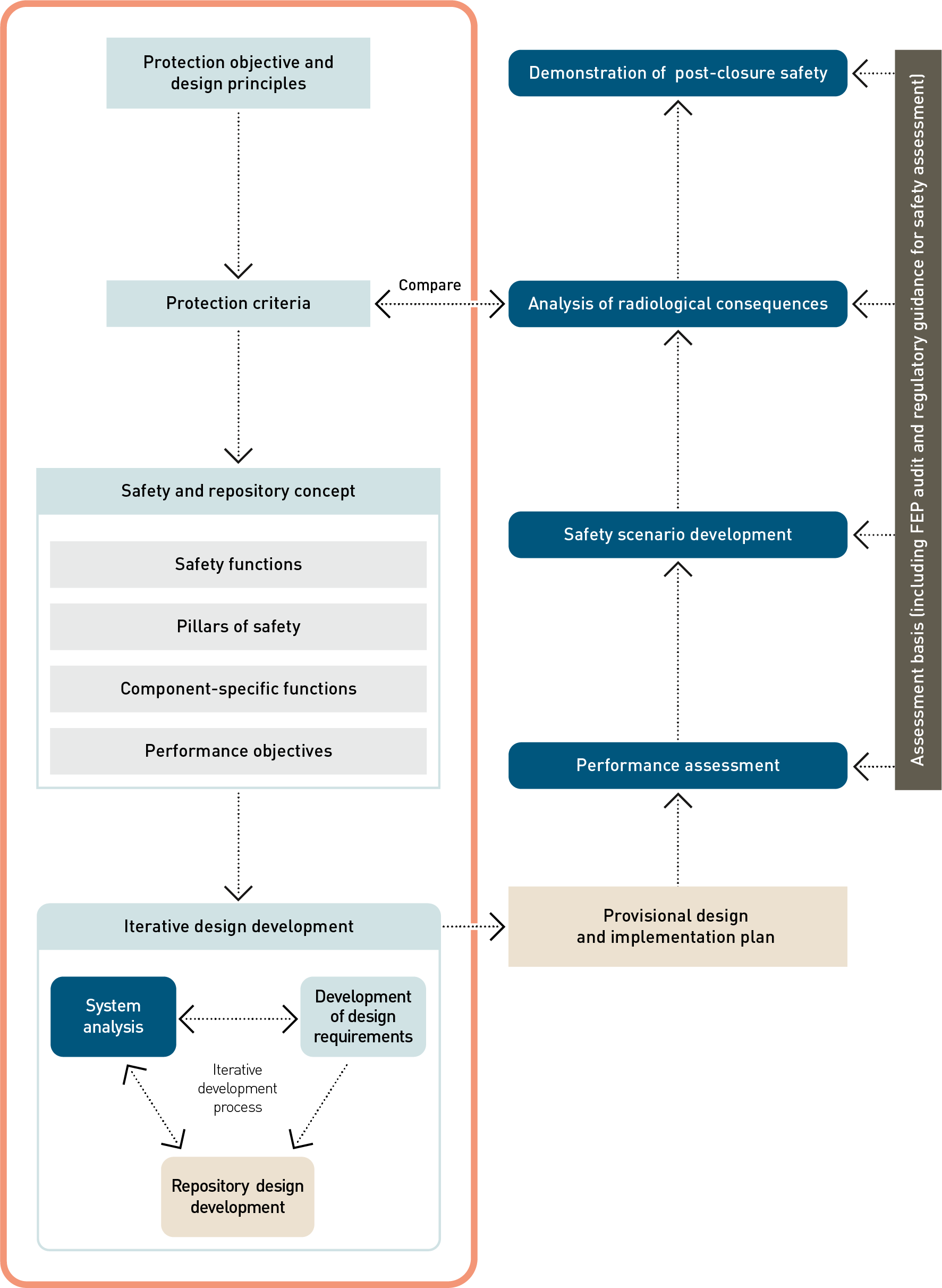
Fig. 3‑1:Workflow for the post-closure safety case, highlighting, in the orange box, the process for developing the current safety and repository concept and a repository design, which then leads to a provisional design and implementation plan
The current safety and repository concept is discussed in detail in NAB 24‑18 Rev. 1 (Nagra 2024s). In the following, we summarise the main aspects with relevance to post-closure safety.
In line with the Swiss legal and regulatory framework, as well as national and international principles and practice (see Chapter 2), the repository provides safety by means of multiple geological and engineered barriers, i.e., it is a multi-barrier system. These barriers operate passively, meaning that, after closure of the repository, no further measures, such as maintenance, control, or monitoring, are required to ensure post-closure safety. This relieves future generations of the burden of having to manage or monitor the repository. The individual barriers contribute to so-called safety functions of the repository system, which together ensure a robust system, as discussed below in Sections 3.2.2 and 3.2.3.
Waste is disposed of in waste emplacement rooms, located deep underground within the Opalinus Clay, between its confining geological units (Fig. 3‑2). The innermost engineered barriers for HLW disposal consist of spent fuel (SF) assemblies with fuel rods (UO2 or mixed oxide fuel (MOX) pellets in cladding tubes) and vitrified HLW from reprocessing of SF (RP-HLW), packaged in steel canisters (NTB 24-20, Nagra 2024d). These HLW disposal canisters are emplaced in drifts, which are subsequently backfilled with a buffer material and sealed. For L/ILW disposal, waste packages for L/ILW are placed inside disposal containers, which are in turn emplaced in caverns that are backfilled with cement-based mortar. The inventory of the waste to dispose of is summarised in Section 5.3.1 and described in detail in NTB 22‑05 (Nagra 2023b).
The geological barrier is of primary importance due to the excellent qualities and long-term geological stability of the containment-providing rock zone (CRZ) (Chapter 5 in NTB 24-17, Nagra 2024i). The CRZ includes the Opalinus Clay host rock, as well as the geological units above and below the host rock layer with similarly favourable properties. The CRZ is delimited in the course of the site selection process according to ENSI 33/649 (ENSI 2018) and documented in NAB 24-01 Rev. 1 (Nagra 2024c).
The Opalinus Clay formation is characterised by:
-
A fine and homogeneous pore structure with a very low hydraulic conductivity. This ensures that water movement in this clay formation is limited, and that radionuclide migration is essentially diffusion-dominated.
-
A high clay-mineral content. This results in a high sorption capacity for many radionuclides, thereby delaying their migration through the clay formation.
-
A high self-sealing capacity. This means that any fractures that may form in the clay formation will rapidly close.
The geological units above and below the Opalinus Clay, albeit with a lower or more heterogeneous clay mineral content, contribute further to the retardation and slow transport of radionuclides.
The depth of the geological barrier is sufficient to limit any potential impact of events and processes at the surface, including erosion, on the safety-related properties of the Opalinus Clay itself and its confining geological units.
The geological barrier is complemented by a mutually compatible set of engineered barriers.
A key role of the engineered barriers is the minimisation and mitigation of disturbances to the CRZ. Such disturbances are inevitably caused by the waste and its emplacement, including, for example, the effects of heat generated by the waste and the disturbance to the rock caused by the excavation and ventilation of underground openings. The engineered barriers around the waste are expected to provide a period of complete containment for at least as long as the heat generated by the waste has significant potential to affect transport processes in the surrounding rock. Eventual release of radionuclides and migration through the multi-barrier system cannot, however, be excluded, although most radionuclides will remain immobilised in the waste packages and waste containers until they decay (see Section 5.4).
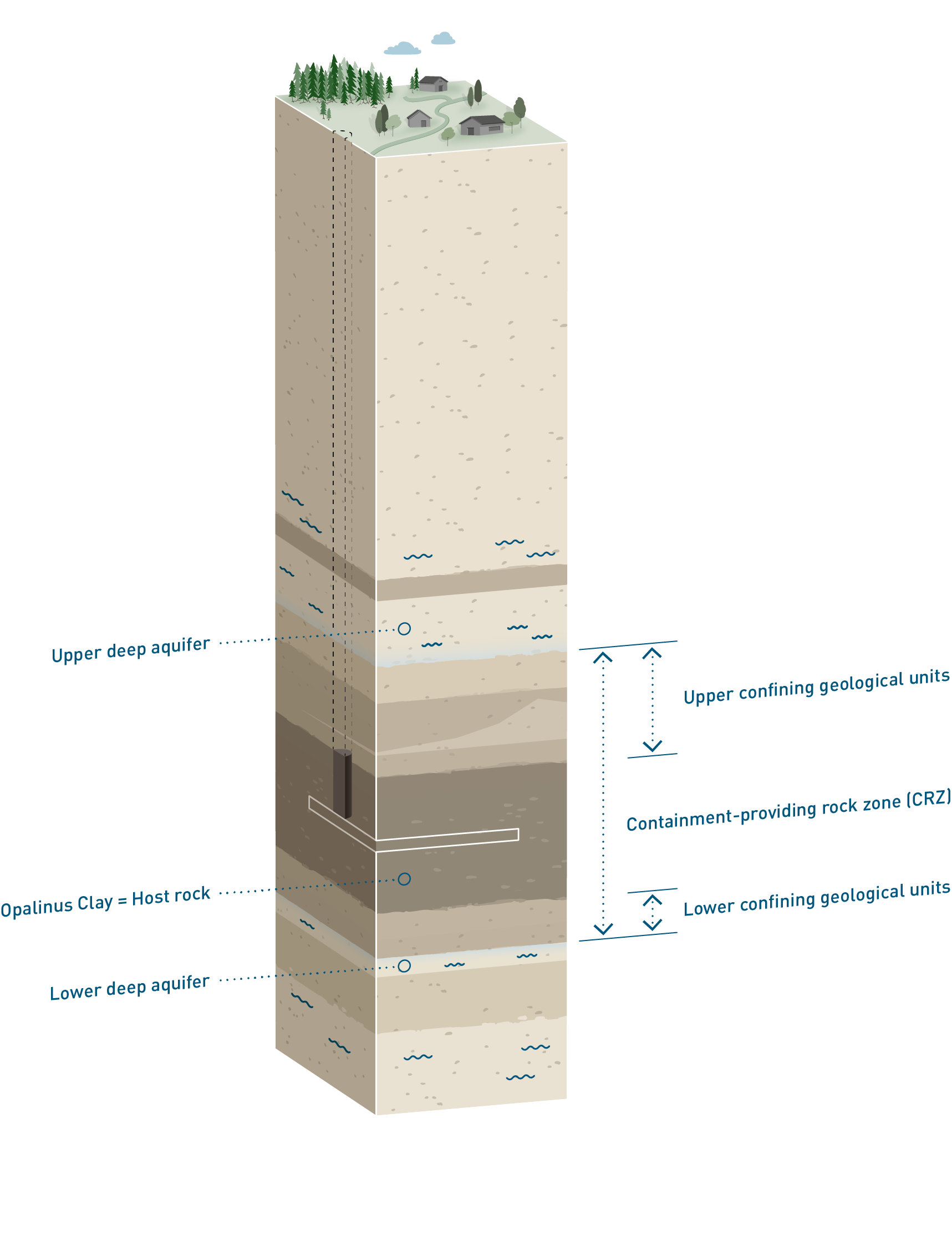
Fig. 3‑2:Placement (white rectangle) of the repository deep underground within the Opalinus Clay, between its confining geological units
Furthermore, the radionuclides that are released will migrate only slowly towards the surface environment, with substantial attenuation by radioactive decay, first within the engineered barriers and then, for any that migrate through these barriers, within the surrounding geological barrier.
The location of the deep geological repository will be such that the risk of future inadvertent human intrusion is small. Nonetheless, inadvertent human intrusion or disturbance of the repository in the distant future cannot be completely excluded, and thus repository design features that mitigate their potential impact also form part of the current safety concept.
Collectively, the multi-barrier system provides the following safety functions:
S1: Isolation of radioactive waste from humans and the environment;
S2: Complete containment of radionuclides for a period of time;
S3: Immobilisation, retention, and slow release of radionuclides;
S4: Compatibility of the components of the repository system;
S5: Long-term stability of the multi-barrier system with regard to long-term geological and climatic evolution.
These safety functions are used to derive a set of safety requirements on the system components, including the “pillars of safety” described below. In the current repository design the safety functions are provided by the elements of the multi-barrier system. Future changes to the system remain possible as there is no single solution for how to provide these safety functions.
Performance assessment, carried out as part of the safety assessment, analyses whether the barriers perform their various functions and thus fulfil their assigned safety functions. Performance assessment is described further in Chapter 6.
The repository barriers and their properties that are the main contributors to these safety functions are termed “pillars of safety”. They are well understood and insensitive to perturbations. The seven pillars of safety are:
-
The deep underground location of the waste emplacement rooms in a stable geological environment that lacks underground resources specific to the region that could attract future human exploitation. It ensures that the repository is not susceptible to geological events and processes relevant to post-closure safety and that inadvertent human intrusion remains unlikely.
-
The containment-providing rock zone (CRZ) includes the host rock as well as upper and lower confining geological units. The host rock, Opalinus Clay, is characterised by a fine and homogeneous pore structure, extremely low hydraulic permeability, a homogeneous and high clay-mineral content and the associated high sorption capacity for many radionuclides. The CRZ is characterised by favourable properties (especially self-sealing ability) for long-term stability, forming a very effective and stable barrier against radionuclide transport and a compatible (physical and chemical) environment for the engineered barriers (NAB 24-18 Rev. 1, Nagra 2024s).
-
Both the SF and RP-HLW matrices are chemically stable in the expected environment.
-
The SF and RP-HLW disposal canisters are mechanically stable and corrosion-resistant in the expected environment. They ensure complete containment of radionuclides for at least as long as the heat generated by the waste has significant potential to affect transport processes in the surrounding barriers. They satisfy the regulatory requirement of complete containment for at least 1,000 years (ENSI 2023).
-
The HLW emplacement drifts will be backfilled with a buffer. This buffer serves as a suitable physical and chemical environment that enhances the longevity of the HLW disposal canisters. Additionally, the buffer offers structural support to the surrounding rock after the degradation of the tunnel support. It compartmentalises the repository by isolating the disposal canisters from one another, thereby mitigating the impact of accidental human intrusion. The buffer reduces the potential effects of heat release on the safety relevant properties of the CRZ and acts as a barrier against radionuclide transport.
-
The L/ILW cementitious near field promotes sorption of radionuclides, decreases corrosion of metals and inhibits degradation of organic materials, which in turn reduces gas generation. The cement-based backfill can also store a significant volume of gas and provides mechanical stability to the host rock, even after the degradation of the tunnel support.
-
The closure system (backfill and seals) provides retention of radionuclides released from the waste packages, and a transport and storage system for repository-generated gas, which retains gaseous radionuclide species within the underground structures while limiting the build-up of gas pressure. The sealing of both the individual waste emplacement rooms and the HLW and L/ILW repository sections reduces safety-relevant interaction between the repository sections and the radiological impact of inadvertent human intrusion. The closure system further provides mechanical stabilisation of the host rock after the rock support has degraded.
Each pillar of safety can contribute directly and/or indirectly to the safety functions. For example, the HLW disposal canisters contribute directly to the containment of radionuclides, while the surrounding buffer contributes indirectly as it helps to protect the canisters. Compatibility between the different pillars of safety is based upon a solid technical and scientific understanding of the geological and engineered components (see Chapter 5).
The contributions of these seven pillars of safety to the five safety functions are summarised schematically in Fig. 3‑3 and Fig. 3‑4 and are elaborated in the discussion of component-specific functions in Section 3.4 of NAB 24-18 Rev. 1 (Nagra 2024s).
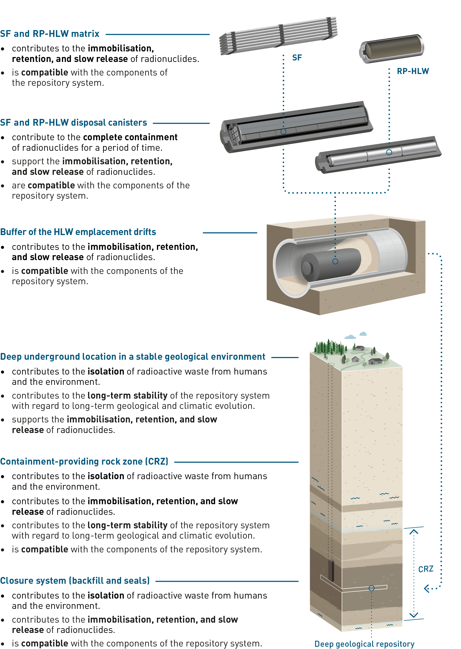
Fig. 3‑3:Summary of the functions of the pillars of safety for HLW disposal in the current repository concept
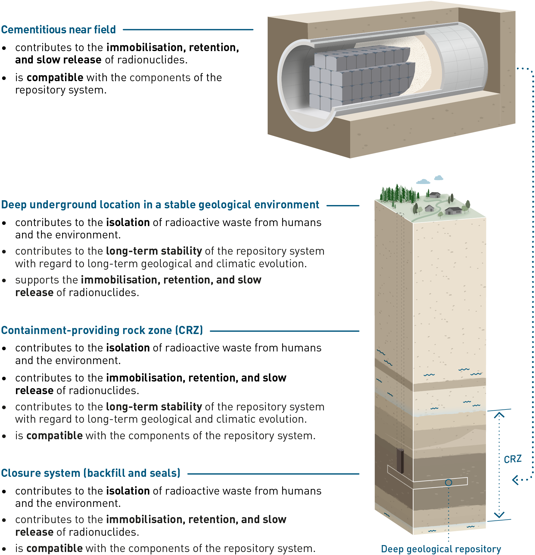
Fig. 3‑4:Summary of the functions of the pillars of safety for L/ILW disposal in the current repository concept
The provisional design for the geological repository, i.e., the implementation of the current safety and repository concept, has been derived from the design principles7 set out in Article 11, Paragraph 2 of the Nuclear Energy Ordinance (KEV 2004) and developed for the purposes of the current licensing step. An overview is given in the following paragraphs; for more details, see Chapter 4 in NAB 24-18 Rev. 1 (Nagra 2024s) and NTB 24-11 (Nagra 2024b). Regarding implementation, it is sufficient to note that procedures for constructing, operating and closing the repository are established, available and affordable. Nevertheless, deviations between the “as-built” state and the “design” specifications must be anticipated, and measures to deal with such situations are foreseen. The safety assessment methodology, with its approach to uncertainty management, contributes significantly to developing such measures.
As illustrated in Fig. 3‑5, the provisional repository design comprises two separate sections: one for the disposal of L/ILW (including ATW), and one for HLW (including both RP-HLW and SF). It will be connected to the surface via three shafts: an access shaft, an operation shaft and a ventilation shaft.
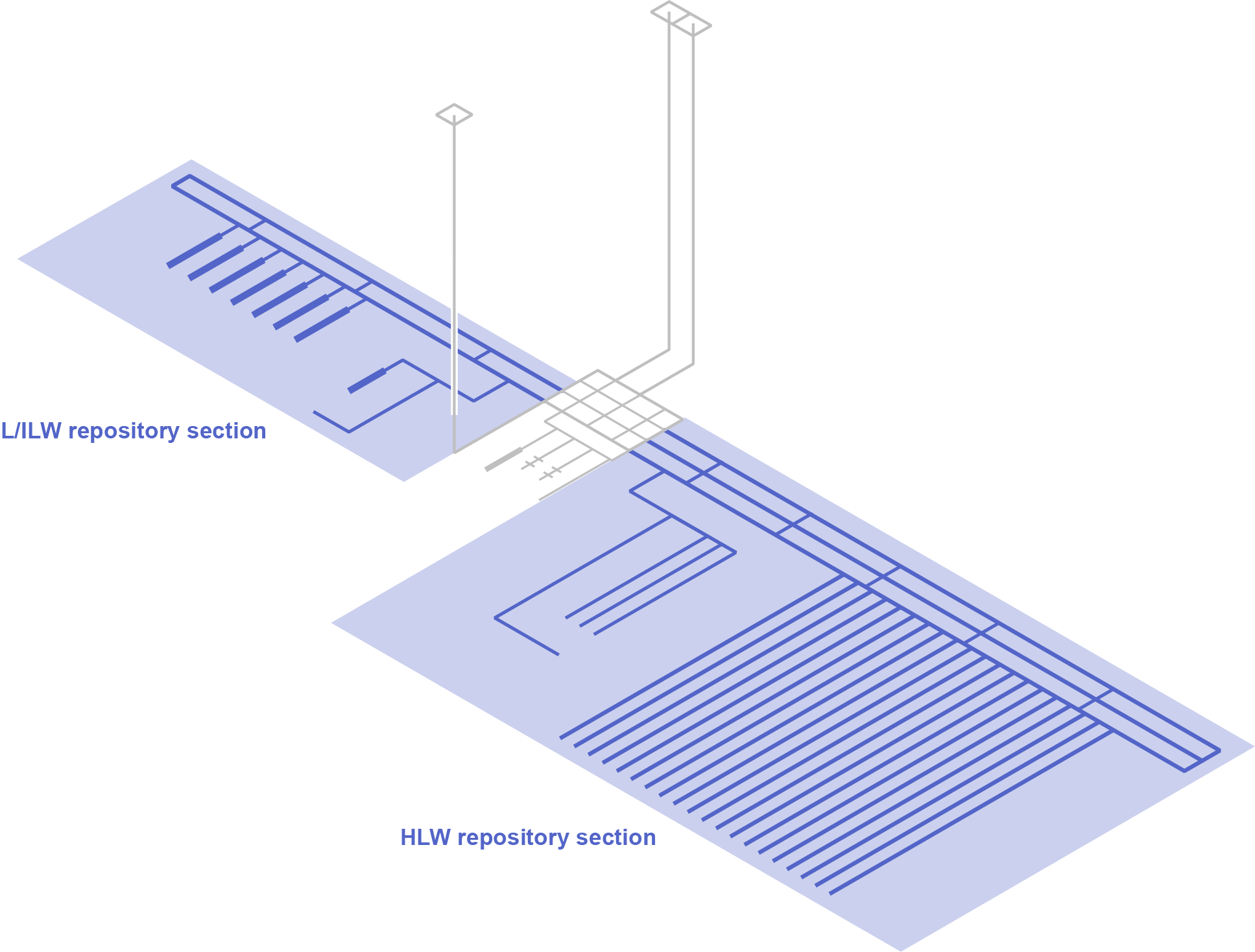
Fig. 3‑5:Representation of two separate repository sections (both coloured in blue) in the provisional design for a deep geological repository for both HLW and L/ILW
A central area will be constructed at the base of the shafts, which will serve as the starting point for the excavation of the L/ILW and HLW repository sections. Repository section accessways connect the shafts and central area to the emplacement rooms. These accessways include an operations tunnel for waste transfer and a ventilation tunnel in both repository sections. A third tunnel is included in the HLW repository section to enable the continuous construction of additional HLW emplacement drifts in parallel with the emplacement of HLW disposal canisters. Continuous construction in parallel with waste emplacement is advantageous for HLW in that it limits the time the emplacement drifts remain open. By contrast, construction of the L/ILW repository section is foreseen to be completed before emplacement operations start, and the tunnel used for the construction can thus also serve as operations tunnel.
Disposal takes place in parallel sets of emplacement rooms (HLW emplacement drifts and L/ILW emplacement caverns). The HLW emplacement drifts are supported by pre-cast concrete tubbing elements (i.e., ring elements). The tunnel support for the L/ILW caverns and other underground openings consists of an outer layer of shotcrete and an inner concrete liner.
The engineered barriers installed within the emplacement rooms are illustrated in Fig. 3‑6.
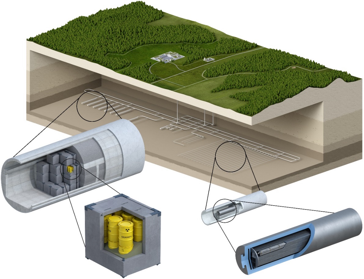
Fig. 3‑6:Conceptual illustration of engineered barriers for the disposal of L/ILW (left) and HLW (right) based on the current repository concept
In addition to the main HLW and L/ILW repository areas, each repository section includes a pilot repository, in which the behaviour of the wastes, the backfill, the seals and the host rock is monitored until the end of a monitoring period. Access to the pilot repositories is via short tunnels that branch from the service tunnels for the main HLW and L/ILW disposal areas.
HLW is encapsulated in carbon steel disposal canisters, placed coaxially along the emplacement drifts, with the surrounding space filled with the buffer material, as illustrated in Fig. 3‑7. The buffer design consists of:
-
prefabricated bentonite blocks, which are placed on the floor of the emplacement drifts; the canisters are then placed on these blocks so that they are in the centre of the drift, and
-
granular bentonite material used to backfill the voids around and between the canisters.
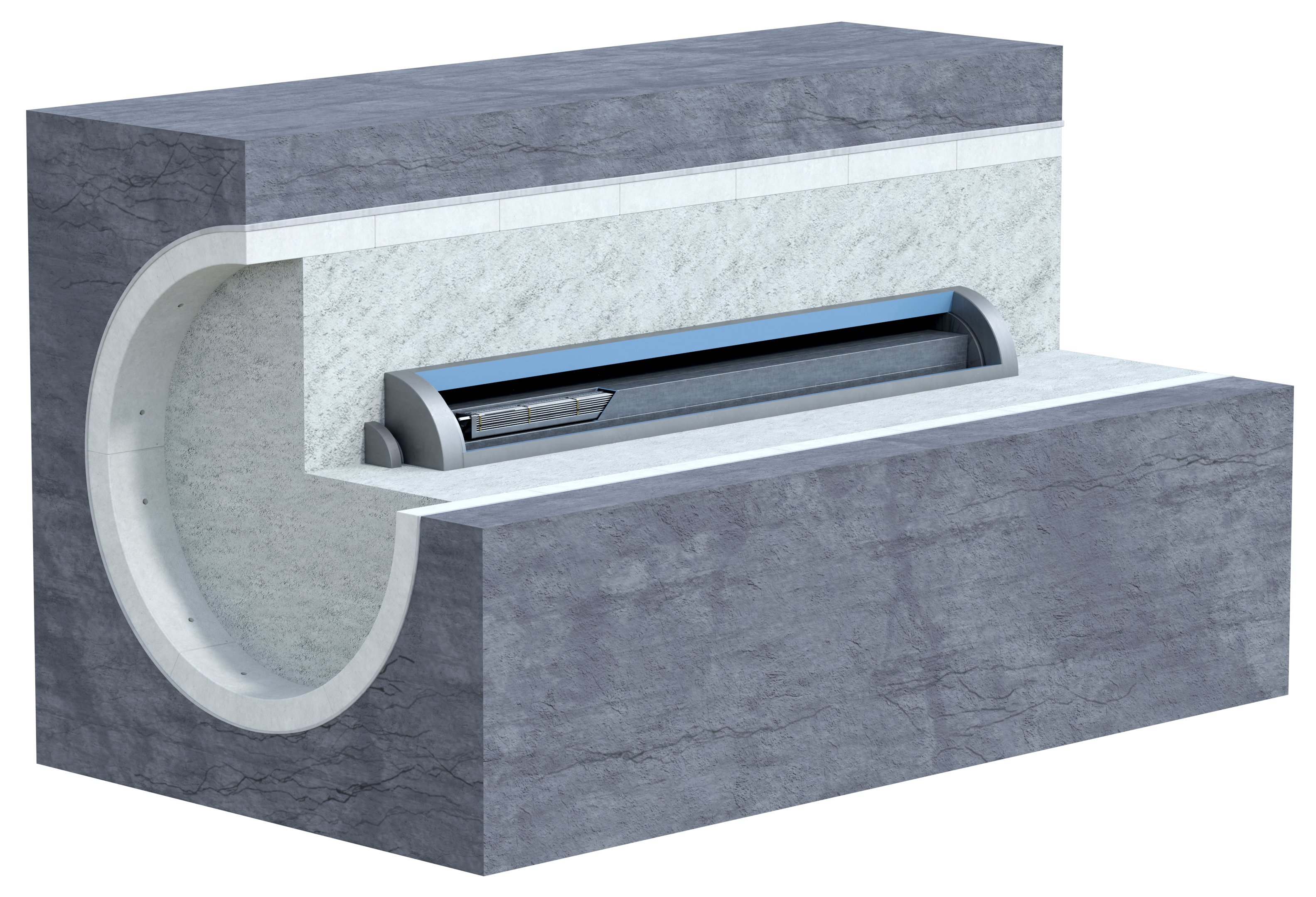
Fig. 3‑7:Schematic representation of an HLW emplacement drift backfilled with bentonite
Most of the L/ILW is compacted, embedded in a cement/mortar matrix and placed in standardised 200 litre drums, MOSAIK-II-type casks made of cast iron, or steel casks. These waste packages are placed inside containers made of reinforced concrete and infilled with a cement-based mortar (Fig. 3‑8).
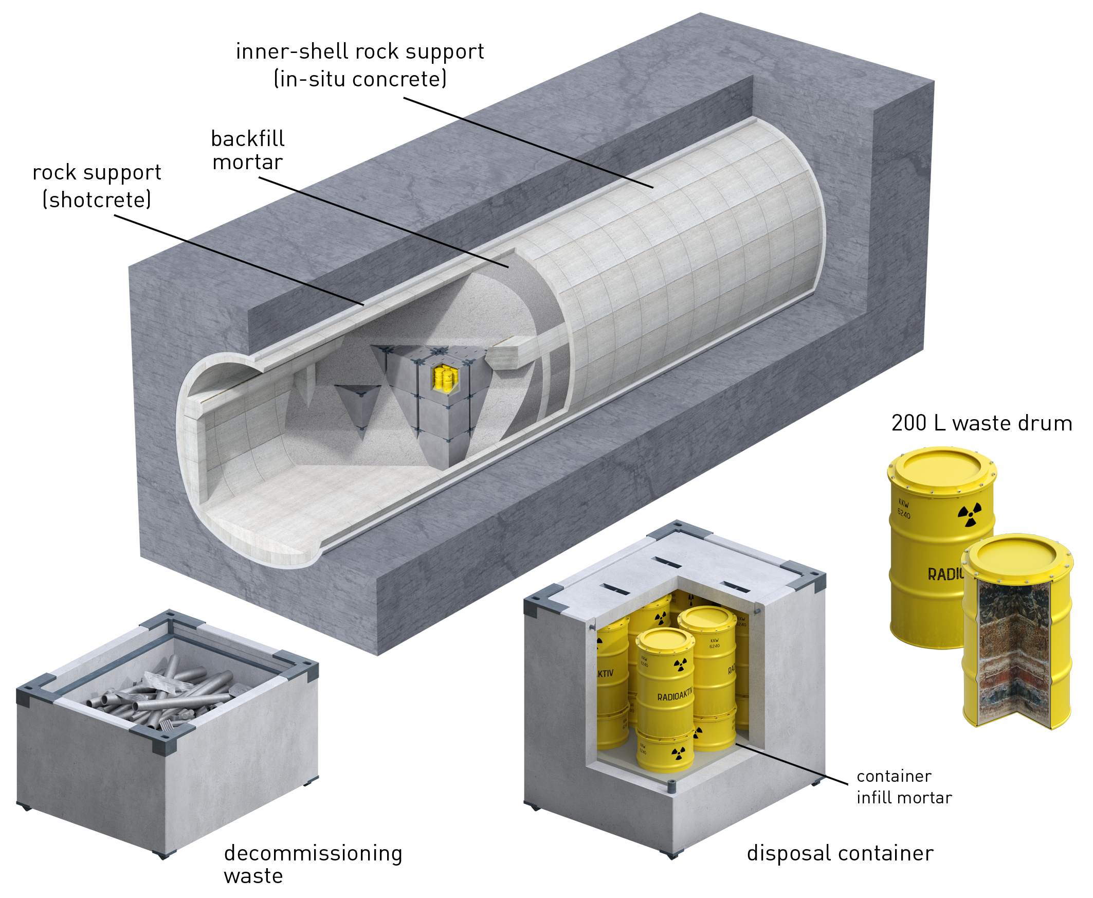
Fig. 3‑8:Examples of L/ILW disposal containers, one filled with directly packaged waste (left), and one containing 200 litre drums (right)
Once the L/ILW containers are emplaced in the caverns, the caverns are also backfilled with a cement-based mortar.
Finally, the closure system is foreseen to consist of various clay-based seals and tunnel backfill. As illustrated in Fig. 3‑9, the seals comprise:
-
V1-HLW and V1-L/ILW seals (emplacement room seals) located at the entrances of the HLW emplacement drifts and L/ILW emplacement caverns, respectively. These seals are installed immediately after emplacement of the waste and the complete backfilling of the emplacement rooms.
-
V2-HLW and V2-L/ILW seals (disposal area access seals) located at the entrances to the pilot repository accessways and the disposal area accessways of the HLW repository section (in the construction, operations and ventilation tunnels) and the L/ILW repository section (in the ventilation and operations tunnel), respectively.
-
V3 seals (shaft seals) located in the shafts up to the top of the Opalinus Clay host rock. These are the outermost seals.
Two types of clay-based backfills, termed VF1 and VF2 (see Fig. 3‑9), fill the repository structures up to the V3 seals. In addition, shaft backfill fills the part of the shafts above the V3 seals up to the surface level (NAB 21-12 Rev. 1, Nagra 2021b).
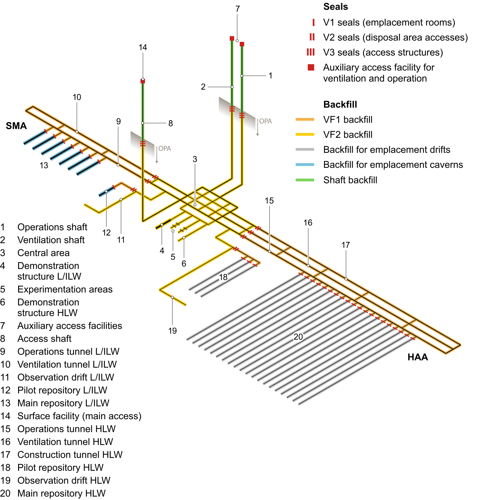
Fig. 3‑9:Schematic view of the underground facilities in the provisional design, including seals and backfill of the repository structures
From NAB 21-12 Rev. 1 (Nagra 2021b).
The V1-HLW, V2-HLW and V3 seals are designed to be both gas- and water-tight. In contrast, the V1-L/ILW and V2-L/ILW seals and the backfill materials are designed with a higher gas permeability to prevent the build-up of potentially damaging gas pressures, due to gas generated by corrosion of metals and degradation of organic materials, predominantly in the L/ILW emplacement caverns.
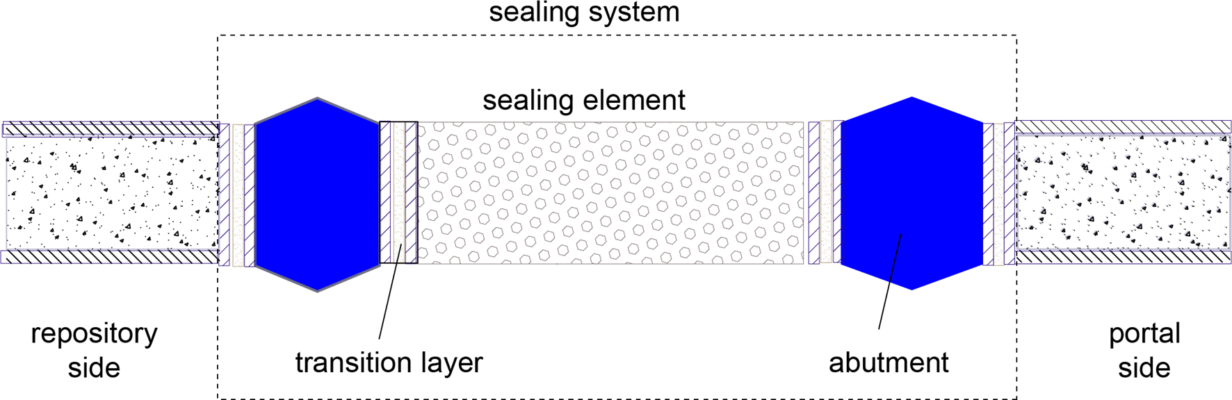
Fig. 3‑10:Generic illustration of a seal, showing its principal components
(not to scale)
The basic design concept is broadly similar for all types of seals and is illustrated in Fig. 3‑10. The principal components of a seal comprise:
-
one or more sealing elements composed of compacted bentonite clay or bentonite/sand,
-
one or more concrete abutments to hold the sealing elements in place, absorbing mechanical stresses and bentonite swelling pressure from the adjacent sealing elements, and
-
one or more transition layers for the purpose of structural design and to provide the physical separation between clay and concrete components.
The design principles for a deep geological repository are set out in Article 11, paragraph 2 of the Nuclear Energy Ordinance of 2004 (KEV 2004). A deep geological repository must be designed to ensure that: a. It complies by analogy with the principles of Article 10 paragraph 1 [Basic principles for the design of nuclear power plants]; b. It guarantees long-term safety through multiple passive safety barriers; c. Steps to ease surveillance and repairs of the repository, or for the recovery of the waste, in no way impair the effectiveness of the passive safety barriers after closure of the repository; d. It can be closed within a period of a few years. Several additional principles and requirements relating to geological disposal defined in the Nuclear Energy Ordinance are listed in NAB 24-18 Rev. 1 (Nagra 2024s). ↩