
The provisional design for the geological repository, i.e., the implementation of the current safety and repository concept, has been derived from the design principles7 set out in Article 11, Paragraph 2 of the Nuclear Energy Ordinance (KEV 2004) and developed for the purposes of the current licensing step. An overview is given in the following paragraphs; for more details, see Chapter 4 in NAB 24-18 Rev. 1 (Nagra 2024s) and NTB 24-11 (Nagra 2024b). Regarding implementation, it is sufficient to note that procedures for constructing, operating and closing the repository are established, available and affordable. Nevertheless, deviations between the “as-built” state and the “design” specifications must be anticipated, and measures to deal with such situations are foreseen. The safety assessment methodology, with its approach to uncertainty management, contributes significantly to developing such measures.
As illustrated in Fig. 3‑5, the provisional repository design comprises two separate sections: one for the disposal of L/ILW (including ATW), and one for HLW (including both RP-HLW and SF). It will be connected to the surface via three shafts: an access shaft, an operation shaft and a ventilation shaft.
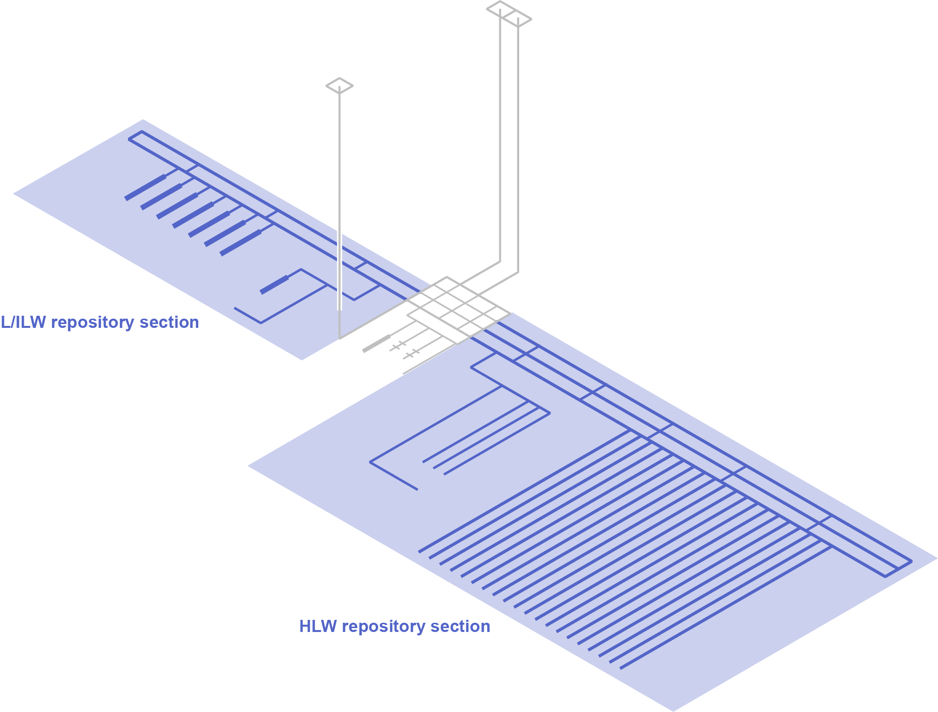
Fig. 3‑5:Representation of two separate repository sections (both coloured in blue) in the provisional design for a deep geological repository for both HLW and L/ILW
A central area will be constructed at the base of the shafts, which will serve as the starting point for the excavation of the L/ILW and HLW repository sections. Repository section accessways connect the shafts and central area to the emplacement rooms. These accessways include an operations tunnel for waste transfer and a ventilation tunnel in both repository sections. A third tunnel is included in the HLW repository section to enable the continuous construction of additional HLW emplacement drifts in parallel with the emplacement of HLW disposal canisters. Continuous construction in parallel with waste emplacement is advantageous for HLW in that it limits the time the emplacement drifts remain open. By contrast, construction of the L/ILW repository section is foreseen to be completed before emplacement operations start, and the tunnel used for the construction can thus also serve as operations tunnel.
Disposal takes place in parallel sets of emplacement rooms (HLW emplacement drifts and L/ILW emplacement caverns). The HLW emplacement drifts are supported by pre-cast concrete tubbing elements (i.e., ring elements). The tunnel support for the L/ILW caverns and other underground openings consists of an outer layer of shotcrete and an inner concrete liner.
The engineered barriers installed within the emplacement rooms are illustrated in Fig. 3‑6.
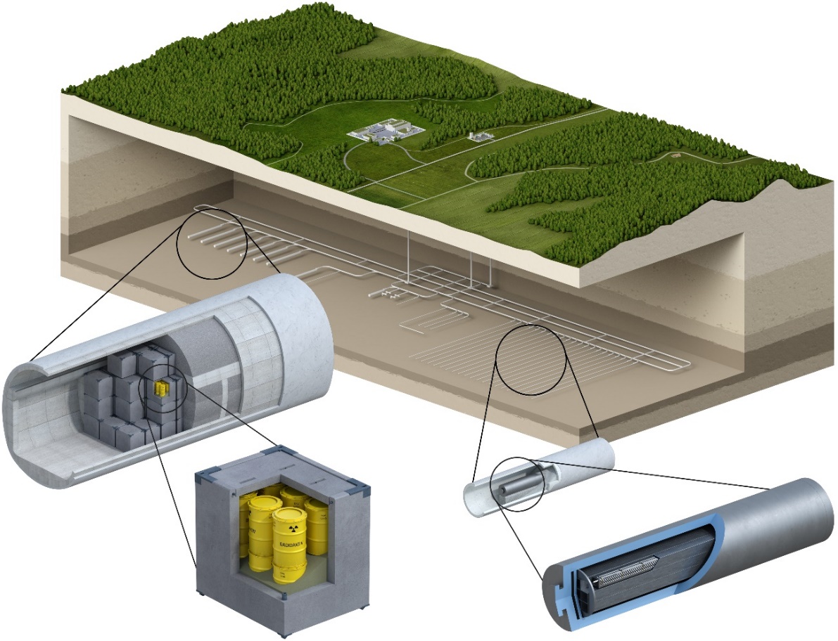
Fig. 3‑6:Conceptual illustration of engineered barriers for the disposal of L/ILW (left) and HLW (right) based on the current repository concept
In addition to the main HLW and L/ILW repository areas, each repository section includes a pilot repository, in which the behaviour of the wastes, the backfill, the seals and the host rock is monitored until the end of a monitoring period. Access to the pilot repositories is via short tunnels that branch from the service tunnels for the main HLW and L/ILW disposal areas.
HLW is encapsulated in carbon steel disposal canisters, placed coaxially along the emplacement drifts, with the surrounding space filled with the buffer material, as illustrated in Fig. 3‑7. The buffer design consists of:
-
prefabricated bentonite blocks, which are placed on the floor of the emplacement drifts; the canisters are then placed on these blocks so that they are in the centre of the drift, and
-
granular bentonite material used to backfill the voids around and between the canisters.
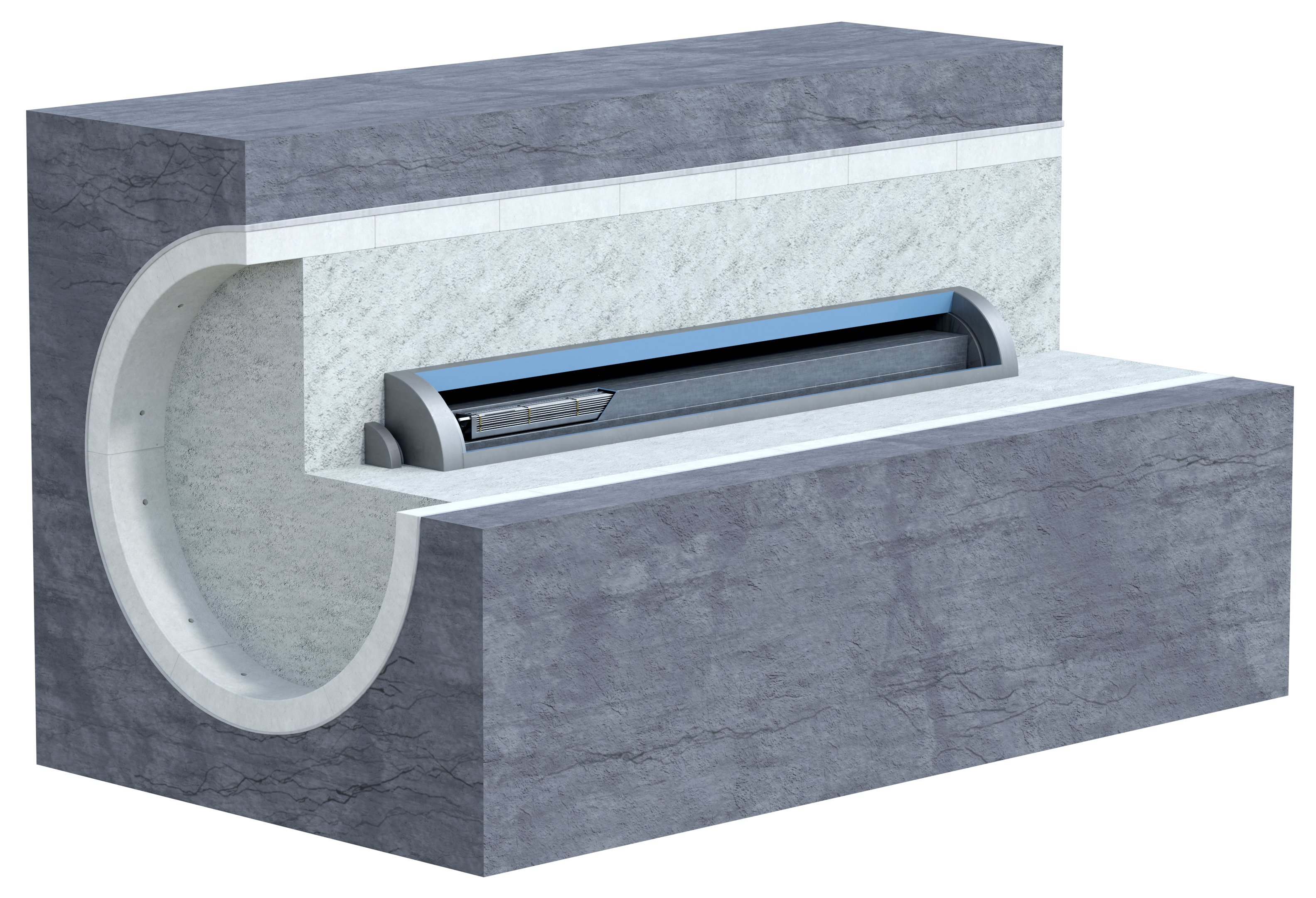
Fig. 3‑7:Schematic representation of an HLW emplacement drift backfilled with bentonite
Most of the L/ILW is compacted, embedded in a cement/mortar matrix and placed in standardised 200 litre drums, MOSAIK-II-type casks made of cast iron, or steel casks. These waste packages are placed inside containers made of reinforced concrete and infilled with a cement-based mortar (Fig. 3‑8).
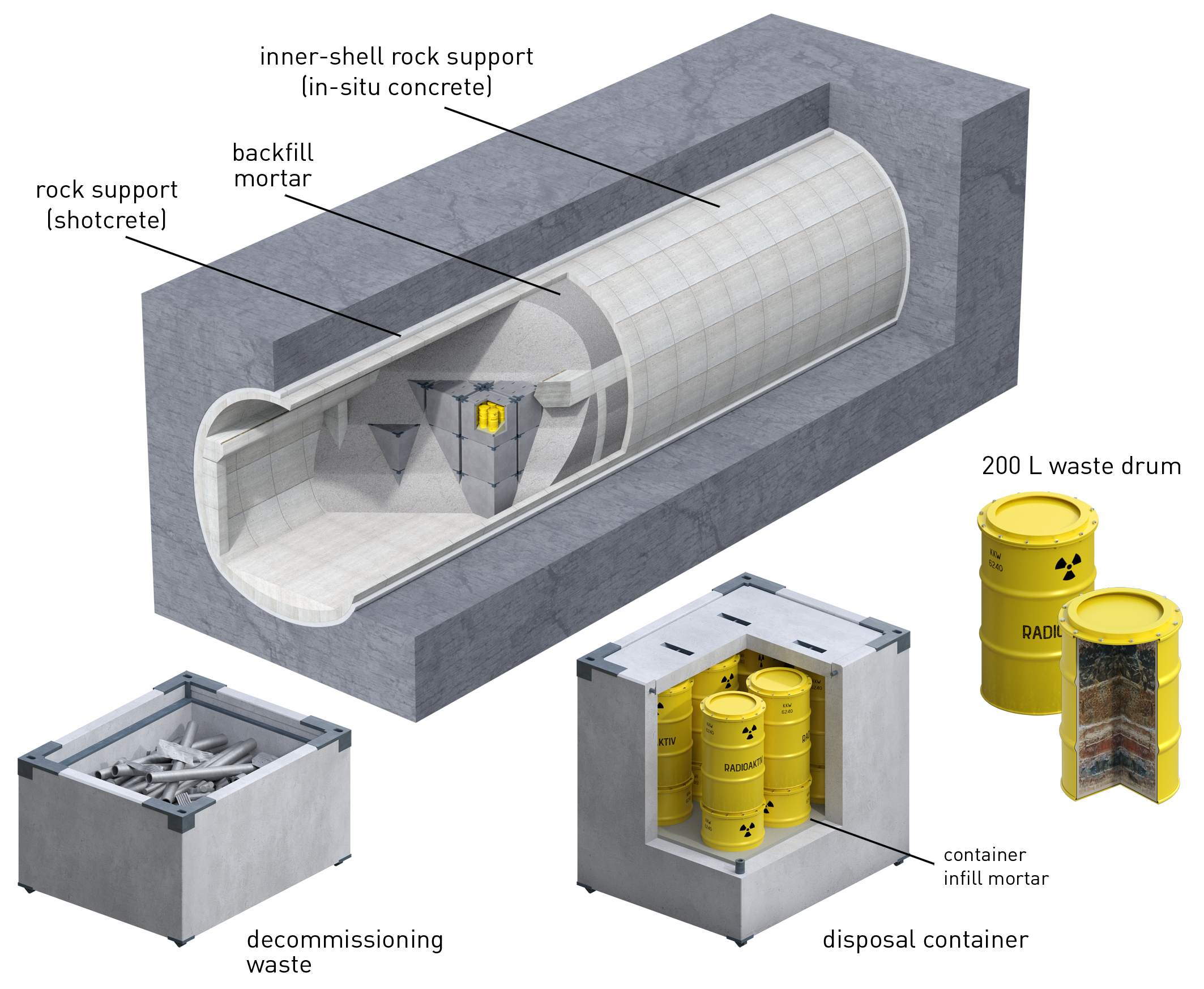
Fig. 3‑8:Examples of L/ILW disposal containers, one filled with directly packaged waste (left), and one containing 200 litre drums (right)
Once the L/ILW containers are emplaced in the caverns, the caverns are also backfilled with a cement-based mortar.
Finally, the closure system is foreseen to consist of various clay-based seals and tunnel backfill. As illustrated in Fig. 3‑9, the seals comprise:
-
V1-HLW and V1-L/ILW seals (emplacement room seals) located at the entrances of the HLW emplacement drifts and L/ILW emplacement caverns, respectively. These seals are installed immediately after emplacement of the waste and the complete backfilling of the emplacement rooms.
-
V2-HLW and V2-L/ILW seals (disposal area access seals) located at the entrances to the pilot repository accessways and the disposal area accessways of the HLW repository section (in the construction, operations and ventilation tunnels) and the L/ILW repository section (in the ventilation and operations tunnel), respectively.
-
V3 seals (shaft seals) located in the shafts up to the top of the Opalinus Clay host rock. These are the outermost seals.
Two types of clay-based backfills, termed VF1 and VF2 (see Fig. 3‑9), fill the repository structures up to the V3 seals. In addition, shaft backfill fills the part of the shafts above the V3 seals up to the surface level (NAB 21-12 Rev. 1, Nagra 2021b).
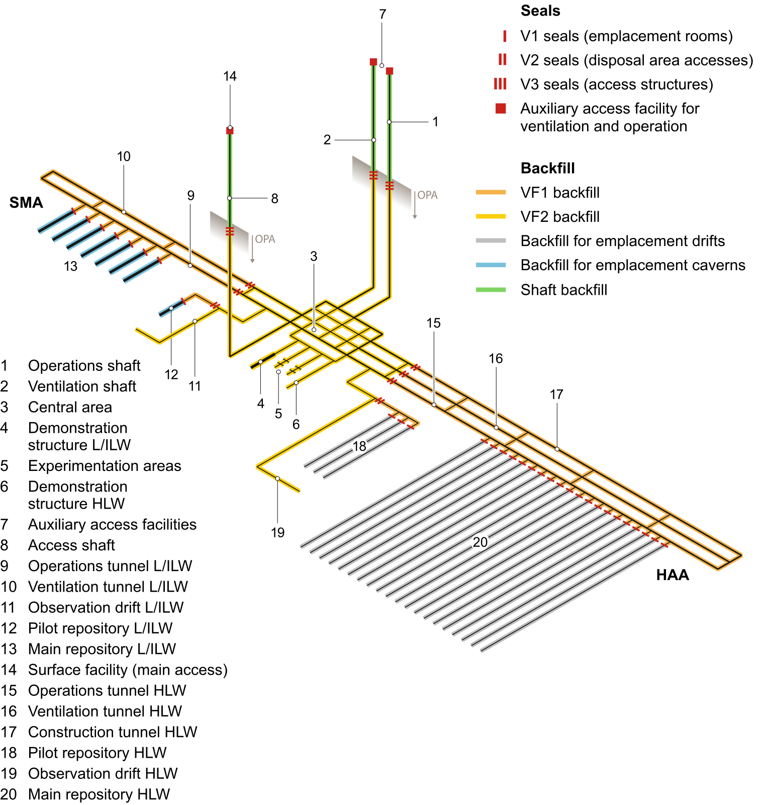
Fig. 3‑9:Schematic view of the underground facilities in the provisional design, including seals and backfill of the repository structures
From NAB 21-12 Rev. 1 (Nagra 2021b).
The V1-HLW, V2-HLW and V3 seals are designed to be both gas- and water-tight. In contrast, the V1-L/ILW and V2-L/ILW seals and the backfill materials are designed with a higher gas permeability to prevent the build-up of potentially damaging gas pressures, due to gas generated by corrosion of metals and degradation of organic materials, predominantly in the L/ILW emplacement caverns.
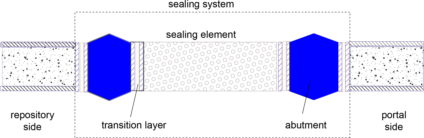
Fig. 3‑10:Generic illustration of a seal, showing its principal components
(not to scale)
The basic design concept is broadly similar for all types of seals and is illustrated in Fig. 3‑10. The principal components of a seal comprise:
-
one or more sealing elements composed of compacted bentonite clay or bentonite/sand,
-
one or more concrete abutments to hold the sealing elements in place, absorbing mechanical stresses and bentonite swelling pressure from the adjacent sealing elements, and
-
one or more transition layers for the purpose of structural design and to provide the physical separation between clay and concrete components.
The design principles for a deep geological repository are set out in Article 11, paragraph 2 of the Nuclear Energy Ordinance of 2004 (KEV 2004). A deep geological repository must be designed to ensure that: a. It complies by analogy with the principles of Article 10 paragraph 1 [Basic principles for the design of nuclear power plants]; b. It guarantees long-term safety through multiple passive safety barriers; c. Steps to ease surveillance and repairs of the repository, or for the recovery of the waste, in no way impair the effectiveness of the passive safety barriers after closure of the repository; d. It can be closed within a period of a few years. Several additional principles and requirements relating to geological disposal defined in the Nuclear Energy Ordinance are listed in NAB 24-18 Rev. 1 (Nagra 2024s). ↩