
This alternative safety scenario assumes the existence of a fault in the vicinity of the repository at the time of its construction that was previously undetected in seismic surveys16. The fault is conservatively assumed to have a transmissivity of 10-10 m2/s. This is one order of magnitude above the highest observed fault transmissivity measured at relevant depths in Northern Switzerland, which occurs in a prominent thrust zone observed in the Schafisheim borehole, well away from the proposed site. Refer to Sections 5.6 and 5.7 of the Geosynthesis of Northern Switzerland in NTB 24‑17 (Nagra 2024i), for detailed discussion.
The fault is conceptualised as a vertical planar feature with a transmissivity that is constant in space and time. Flow of water through the fault is assumed to occur vertically upwards from the deep aquifers underlying the repository (Keuper and Muschelkalk) to the deep aquifer above the repository (Malm). Conceptualising the fault as vertical planar feature with constant properties and connecting the upper and lower deep aquifers is a simplification of reality that is highly conservative.
The vertical Darcy flow in the fault is determined using PA models as described in NAB 24-25 (Nagra 2024k), with a hydraulic gradient of less than about 1 m/m. According to the hydrogeological knowledge described in Section 4.4. of the Geosynthesis of Northern Switzerland in NTB 24‑17 (Nagra 2024i), this assumption is conservative.
Two variants are considered, where the fault intersects the emplaced waste in either the HLW or the L/ILW repository sections. For each variant, two calculation cases are defined. When the fault strike is parallel to the emplacement rooms (cases AS-FLT-HLW-Along and AS-FLT-L/ILW-Along), the fault is assumed to pass through one, single emplacement room. When the fault strike is perpendicular to the emplacement rooms (cases AS-FLT-HLW-Across and AS-FLT-L/ILW-Across), the fault is assumed to pass through all emplacement rooms in the respective disposal area (but not the emplacement rooms of the pilot repository). These different fault configurations are illustrated in Fig. 7‑5.
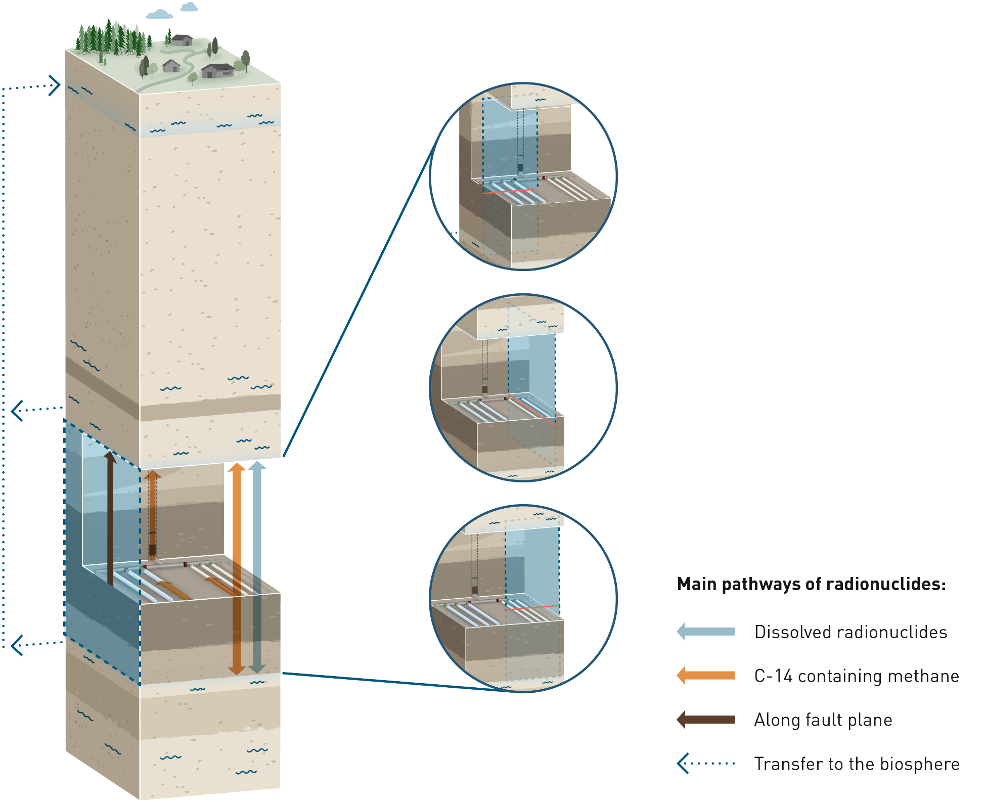
Fig. 7‑5:Pathways for radionuclide transport where the existence of an undetected fault is assumed, which intersects one or more L/ILW emplacement caverns or HLW emplacement drifts
The small inset figures show different ways in which the fault is conceived to impact these repository features in the modelling carried out for the calculation of radiological consequences.
The fact that such a fault would most likely be detected during construction and that technical measures would be implemented accordingly is disregarded in this scenario. ↩