
Safety scenario development, as part of the general safety assessment workflow, is illustrated in Fig. 7‑1.
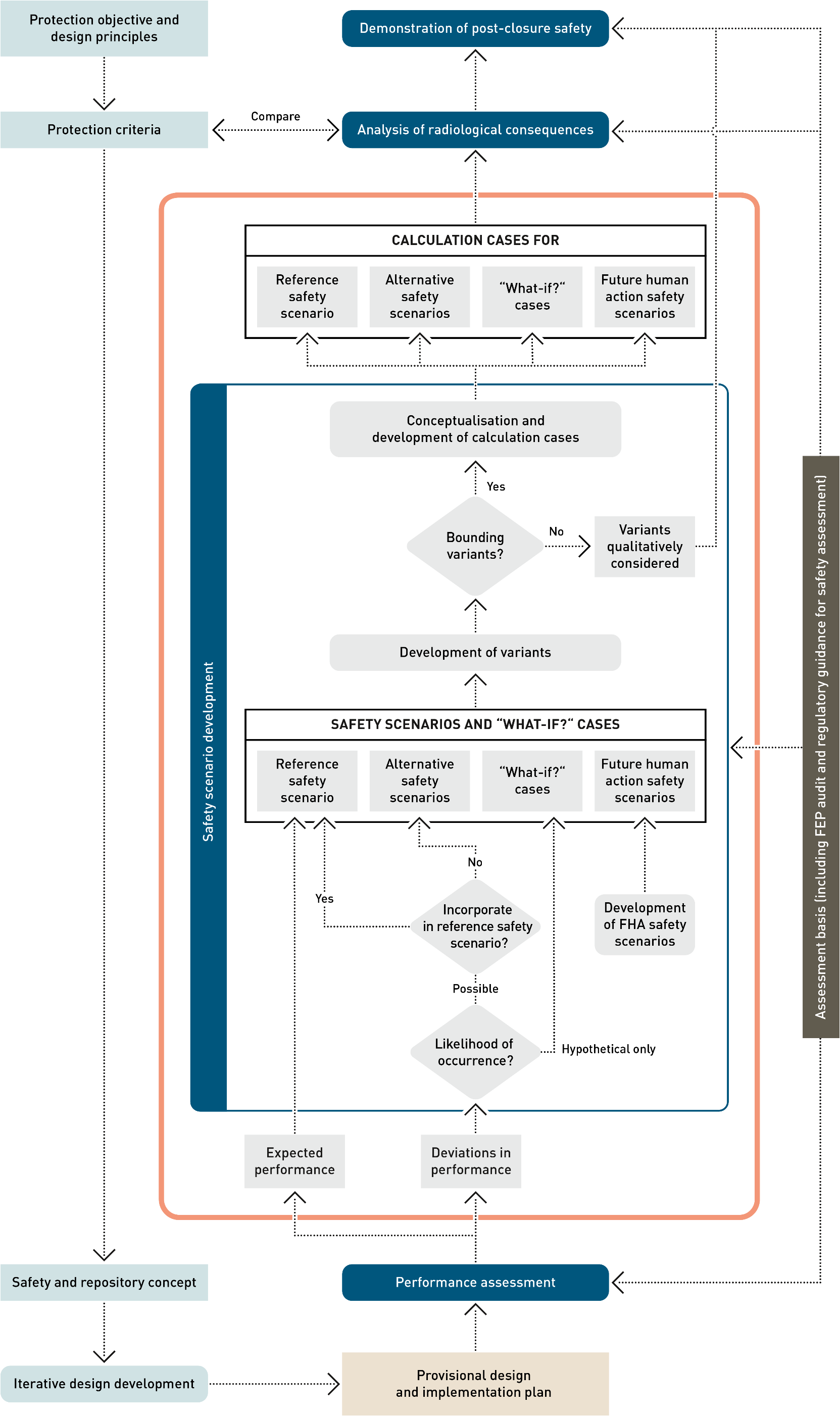
Fig: 7-1Workflow for the post-closure safety case, highlighting, in the orange box, the main elements of the safety scenario development process
Consistent with international and national guidelines, safety scenarios are defined that describe both the expected evolution of the repository and the barriers over the one-million-year time period for assessment, and also less likely and hypothetical evolutions and deviations in performance as identified in the assessment basis and the PA as well as others resulting from future human actions. Specifically, safety scenario development involves the definition of:
- A reference safety scenario
The reference safety scenario is a general description of the expected initial state of the repository barriers, their expected evolution over time, including the release, retention and transport of radionuclides within the repository system, and the assumptions made regarding the biosphere for the analysis of radiological consequences.
- A set of alternative safety scenarios
The alternative safety scenarios include deviations in performance that are judged unlikely, or highly unlikely, but scientifically non-excludable evolutions, on the basis of the assessment and the findings of PA, and lead to a general description of the initial state of the repository barriers and their evolution over time that differs substantially from that of the reference scenario.
- A set of hypothetical “what-if?” cases
Deviations in performance that are judged to be impossible, at least in the one-million-year period for assessment, i.e., which are outside the range of possibilities supported by currently available evidence and knowledge, may nonetheless be propagated to the analysis of radiological consequences as hypothetical “what-if?” cases, designed to demonstrate the robustness of the repository system. As well as “what-if?” cases based on extreme assumptions regarding actual physical phenomena, additional hypothetical “what-if?” cases are also defined that postulate a degraded performance of each of the pillars of safety, unconnected to any physical phenomena. As noted in Section 4.5, they can mitigate possible “completeness uncertainty”, pre-empting possible criticism that some detrimental FEPs are either unknown or have been overlooked.
- A set of safety scenarios considering future human actions (FHAs).
The safety scenarios considering future human action concern the long-term impact of potential actions undertaken by human society on the performance and safety of the repository. They are handled in a broadly similar manner to the alternative safety scenarios but are treated as a separate class of safety scenarios, due to their particularly speculative nature. The main difference in their development compared with the alternative safety scenarios is that, instead of being derived from the assessment basis and deviations in performance identified in the PA, they are derived from FHA FEPs within the FEP database, which are screened to identify those with the potential to perturb the pillars of safety and their safety functions. A full description of Nagra’s methodology for FHAs in the general licence application, its application, and the assessment of the identified FHA safety scenarios can be found in Chapter 2 of NAB 24-09 (Nagra 2024r).
Having defined the safety scenarios, the main elements of uncertainty are identified that, depending on how they are conceptualised within a given safety scenario, could affect the radiological consequences of the scenario. These can include the extent or timing of key phenomena associated with a safety scenario as well as positioning or properties of a key feature. In general, the conceptualisations that are expected to give rise to the highest radiological consequences are taken as the scenario variants that are propagated to the analysis of radiological consequences.
Calculation cases are then defined for each safety scenario variant. This generally requires a degree of geometrical simplification, or abstraction. There may be different ways in which this abstraction can be performed, in which case, especially if the most conservative abstraction cannot be judged in advance of the calculations, more than one calculation case for a given safety scenario variant may be propagated to the analysis of radiological consequences. Additional calculation cases, including probabilistic analyses, are also defined to quantify the effects of parameter uncertainty; see Chapter 8 for details. Several individual calculations may be performed for each calculation case that is propagated to radiological consequence analysis. In particular, different model concepts and models are used for radionuclide transport pathways in the liquid phase on the one hand and two-phase flow and transport of 14C on the other (see Chapter 8 in NAB 24-07 Rev. 1, Nagra 2024w and additional details given in Appendix B of NTB 24-18, Nagra 2024p).
Deviations in performance arising from almost all PA scenarios are incorporated within, or propagated to, one or more safety scenarios and “what-if?” cases, as illustrated in Tab. 7‑1. The difference between safety scenarios and “what-if?” cases on the one hand and PA scenarios on the other is that safety scenarios and “what-if?” cases focus on the properties of the system and their evolution as they affect waste isolation and radionuclide release, retention, transport and radiological consequences. Thus, there is, for example, a “what-if?” case in which a fault is created at some time in the future, and the description given in the present chapter focusses on what this means in terms of radionuclide transport pathways, rather than what could lead to faulting in the first place. The PA scenarios, on the other hand, address events and processes that could potentially degrade the barriers and their safety functions leading to deviations in performance, including phenomena like earthquake, gas pressurisation and thermal stresses that could lead to faulting. Thus, several PA scenarios can be captured by just one (alternative) safety scenario or “what-if?” case, as can be seen in the table. There are also multiple PA scenarios that are captured by the reference safety scenario, through the ranges of parameter values considered in the analysis of this scenario, since the PA scenarios that are captured affect, e.g., the rates of certain processes, but do not fundamentally affect the broad evolution of the pillars of safety. Note that the hypothetical ZEROGAS PA scenario is not directly included in the reference safety scenario parameter ranges. Its impact is, however, considered implicitly through the conservative assumption of fully saturated conditions employed for the modelling of aqueous transport of radionuclides in the analysis of radiological consequences (see Chapter 8 and Appendix A in NTB 24-18, Nagra 2024p).
Further combinations of PA scenarios not captured by the present safety scenarios, or the combination of a PA scenario and an FHA FEP, could, in principle, be conceivable. However, the likelihood of such combinations, though not evaluated quantitatively, is so low that they could, in effect, be considered as “what-if?” cases. Furthermore, the consequences of PA scenarios and FHA FEPs considered individually can, in some instances, be greater if they are considered in combination. For example, the presence of an undetected fault, which is considered as an alternative safety scenario, will lead to reduced gas pressures in the repository, which would lessen the impact of gas-mediated transport of 14C in the event of a borehole later being drilled and penetrating the repository underground structures. In practice, the consequences of such combinations are, in any case, bounded by the extreme “what-if?” cases mentioned above.
The comprehensiveness of the safety scenarios described in this chapter is assessed as part of the wider assessment of the comprehensiveness of the post-closure safety case carried out by means of the FEP audit (see Section 5.5).
Tab. 7‑1:Incorporation of PA scenarios in safety scenarios and “what-if?” cases
Colouring indicates whether a PA scenario is incorporated in the reference safety scenario, an alternative safety scenario, or a “what-if?” case.
|
Performance assessment scenarios |
Safety scenarios |
“What-if?” cases
|
||||||
|
Reference safety scenario |
Alternative safety scenarios |
Related to physical phenomena |
Hypothetical degraded performance of pillar of safety |
|||||
|
Hydraulically active confining geological unit |
Undetected fault |
Undetected fault with hypothetically high transmissivity |
Future creation or reactivation of a fault |
Repository excavation |
||||
|
EXPERF |
Expected performance |
RS |
||||||
|
MKALK |
Exfiltration to Muschelkalk |
RS-KEUPER_ INACTIVE |
||||||
|
UPFLOW |
Upflow with artesian pressure in Keuper |
|
||||||
|
DWNFLW |
Downflow with artesian pressure in Malm |
|
||||||
|
HETOPA |
Heterogeneous Opalinus Clay |
|
||||||
|
PESSGAS |
Pessimistic gas generation rate (L/ILW) |
|
||||||
|
UBGAS |
Upper bound gas source term (HLW) |
|
||||||
|
V3PERM |
Highly permeable V3 seals |
|
WI-V3 |
|||||
|
HARDBED |
Hard beds as release paths |
AS-HA |
||||||
|
HERWIS |
«Herrenwis Unit» as release path |
AS-HA/CD |
||||||
|
FLTHLWP |
Undetected fault parallel to HLW drifts |
AS-FLT-HLW-Along |
WI-FLT-HLW-Along |
|||||
|
FLTHLWN |
Undetected fault normal to HLW drifts |
AS-FLT-HLW-Across |
WI-FLT-HLW-Across |
|||||
|
FLTLILW |
Undetected fault affecting L/ILW caverns |
AS-FLT-L/ILW |
WI-FLT-L/ILW |
|||||
|
UBHEAT |
See RIEHLW |
WI-FLT/RA-HLW |
||||||
|
RIEHLW |
Thermally- and gas-induced faulting (HLW) |
WI-FLT/RA-HLW |
||||||
|
RIELILW |
Gas-induced faulting (L/ILW) |
WI-FLT/RA-L/ILW |
||||||
|
SEISHLW |
Earthquake affecting HLW drifts |
WI-FLT/RA-HLW |
||||||
|
SEISLILW |
Earthquake affecting L/ILW caverns |
WI-FLT/RA-L/ILW |
||||||
|
LOSSFLT |
Fault activation due to overburden loss |
WI-FLT/RA |
||||||
|
LOSSOB |
Permeability increase due to overburden loss |
not explicitly represented |
||||||
|
IRMAX |
Instant release of entire I-129 activity |
WI-SF-IRF |
||||||
|
WPFAIL |
Canister failure at time of repository closure |
WI-HLW-CAN |
||||||
|
ZEROGAS |
No gas generation |
not addressed |
||||||