
Three groups of “what-if?” cases related to physical phenomena are described below and considered in the analysis of radiological consequences.
-
Occurrence of an undetected fault with a hypothetically high transmissivity in the vicinity of the repository
This set of “what-if?” cases is almost identical to the alternative safety scenario of an undetected fault but assumes the presence of an undetected fault in the vicinity of the repository with a transmissivity that is much higher than could reasonably be expected: 10‑7 m2/s, which is three orders of magnitude higher than that of the fault considered in the alternative safety scenario described in Section 7.3.2. This is similar to fault transmissivities observed in the thin competent, horizonal limestone features, e.g., the “hard beds”, embedded between more plastic clay rock units within the CRZ; see Section 5.6 of the Geosynthesis of Northern Switzerland in NTB 24‑17 (Nagra 2024i). It is four orders of magnitude above the highest observed fault transmissivity measured at relevant depths in Northern Switzerland, which occurs in a prominent thrust zone observed in the Schafisheim borehole, well away from the proposed site (Section 5.6 of NTB 24-17, Nagra 2024i).
As in the corresponding alternative safety scenario, the fault is represented, for reasons given earlier (Section 7.3.2), as a vertical planar feature with a transmissivity that is constant in space and time. Flow of water through the fault is assumed to occur vertically upwards from a deep aquifer underlying the repository (the Keuper or Muschelkalk) to the Malm aquifer above the repository.
As in the corresponding alternative safety scenario, two variants (fault intersecting either the HLW or the L/ILW disposal area) with two calculation cases each are considered: when the fault strike is parallel to the emplacement rooms (cases WI-FLT-HLW-Along and WI-FLT-L/ILW-Along), the fault is assumed to pass through one, single emplacement room. When the fault strike is perpendicular to the emplacement rooms (cases WI-FLT-HLW-Across and WI-FLT-L/ILW-Across), the fault is assumed to pass through all emplacement rooms in the respective repository section (but not the emplacement rooms of the pilot repositories). These different fault configurations are the same as those shown in Fig. 7‑5.
-
Future creation or reactivation of a fault either by geological processes or as a repository-induced effect after repository closure
A second set of “what-if?” cases is defined that assumes the generation of a new fault or the re-activation of an existing, non-transmissive fault, during the post-closure period. Faulting or fault reactivation are assumed to occur as the result of stress changes induced either by geological processes, such as seismic activity, or by heat or gas generated within the repository. The transmissivity of the fault is again assumed to be 10‑7 m2/s.
As above, the fault is again represented as a vertical planar feature with a transmissivity that is constant in space and time. Flow of water through the fault is assumed to occur vertically upwards from a deep aquifer underlying the repository (the Keuper or Muschelkalk) to the Malm aquifer above the repository.
Again, two variants are considered, where the fault intersects either the HLW or the L/ILW disposal area. The fault is anticipated to be created or re-activated at 10,000 years post-closure in cases where the fault intersects the HLW repository section. The timing corresponds with the assumed canister breaching time, leading to conservative estimations of the consequences. Faulting or fault re-activation could also result in a degraded performance of the bentonite buffer which is considered in these calculation cases. In cases where the fault intersects the L/ILW repository section, 20,000 years is selected, as it is the earliest time when, according to performance assessment, a gas overpressure could occur in the L/ILW emplacement caverns (Fig. 6‑9), again leading to conservative estimations of consequences. There could be damage to the L/ILW near field as a result of faulting/fault re-activation, but this would be unlikely to affect radiological consequences, given that substantial mechanical degradation of the L/ILW cavern backfill cannot, in any case, be excluded by this time and is implicitly assumed in the analysis of radiological consequences, in which the contents of each cavern are assumed to be well mixed.
Finally, for each variant two calculation cases similar to those above are defined: when the fault strike is parallel to the emplacement rooms (cases WI-FLT/RA-HLW-Along and WI-FLT/RA-L/ILW-Along), the fault is assumed to pass through one, single emplacement room. When the fault strike is perpendicular to the emplacement rooms (cases WI-FLT/RA-HLW-Across and WI-FLT/RA-L/ILW-Across), the fault is assumed to pass through all emplacement rooms in the respective repository section (but not the emplacement rooms of the pilot facilities). These different fault configurations are again the same as those shown in Fig. 7‑5.
-
Excavation of the repository by erosive processes
In the very long term, uplift and erosion by both glacial and non-glacial (fluviatile) processes will bring the repository closer to the surface; this phenomenon is included in the reference safety scenario. During the first one million years, the effects on the performance of the repository system are expected to be negligible (Chapters 3 and 6 of NTB 24-22 Rev. 1, Nagra 2024u).
In the more distant future, there is, however, the potential for repository material to be excavated by glacial and non-glacial erosion processes (Section 6.4 of NTB 24-17, Nagra 2024i). In Fig. 7‑6, the erosion processes affecting the rock overlying the repository are shown, with fluvial incision due to the uplift and the evolution of the local topography (e.g., due to hillslope processes) comprising the non-glacial erosion processes.
Even though excavation of the repository by erosive processes is predicted to be possible only after the one-million-year time period for assessment, Nagra is, nonetheless, required by ENSI Guideline ENSI 33/649 (ENSI 2018) to analyse such events as part of the safety assessment. An “excavation of the repository by erosive processes” is thus categorised as a “what-if?” case and analysed in the safety assessment. The conceptualisations and the corresponding analysis of the radiological consequences are described in detail in NAB 24-08 Rev. 1 (Nagra 2024q).
The variants and calculation cases are grouped by the two main erosion processes, glacial erosion and non-glacial erosion:
-
Three variants are defined for the glacial erosion, reflecting the three distinct post-glacial configurations: river, lake, and spring. The river variant is developed into two calculation cases, whereas lake and spring variants have one calculation case each.
-
For non-glacial erosion two variants are defined: erosion of the repository on the hillside and erosion of the repository at the valley floor. The former has four calculation cases (reflecting different hillslope angles), whereas the latter has one calculation case.
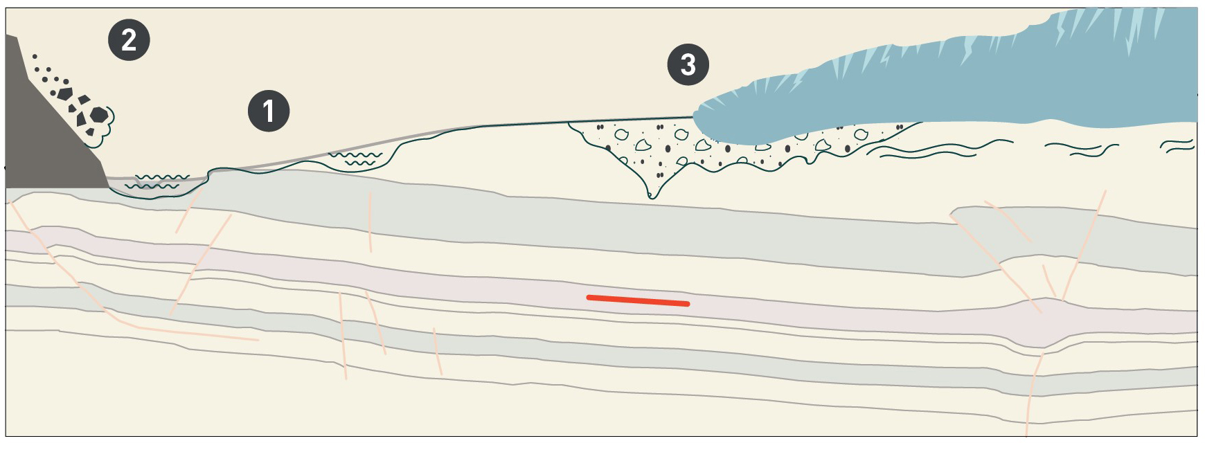
Fig. 7‑6:Illustration of erosion processes affecting the rock overlying the repository (red bar), simplified from Figure 6-1 of NTB 24-17 (Nagra 2024i)
1: Fluvial incision; 2: Evolution of local topography; 3: deep glacial erosion