
Whereas the clay-mineral content exerts strong control on the swelling capacity of the Opalinus Clay (Section 5.5.2), a sufficient overburden thickness (Section 5.6.3) or critical effective normal stress is also required for robust self-sealing.
Experiments at Mont Terri and the Tournemire rock laboratories have shown that a relevant increase in fracture transmissivity is only obtained at very low effective normal stress on the fracture surface (Marschall et al. 2017, Donzé et al. 2023, Guglielmi et al. 2020) (Fig. 5‑47). This "threshold" is referred to as fracture opening pressure (FOP) and was constrained at approximately 1 – 2 MPa. In Fig. 5‑47, FOP is indicated in terms of the corresponding effective stress level.
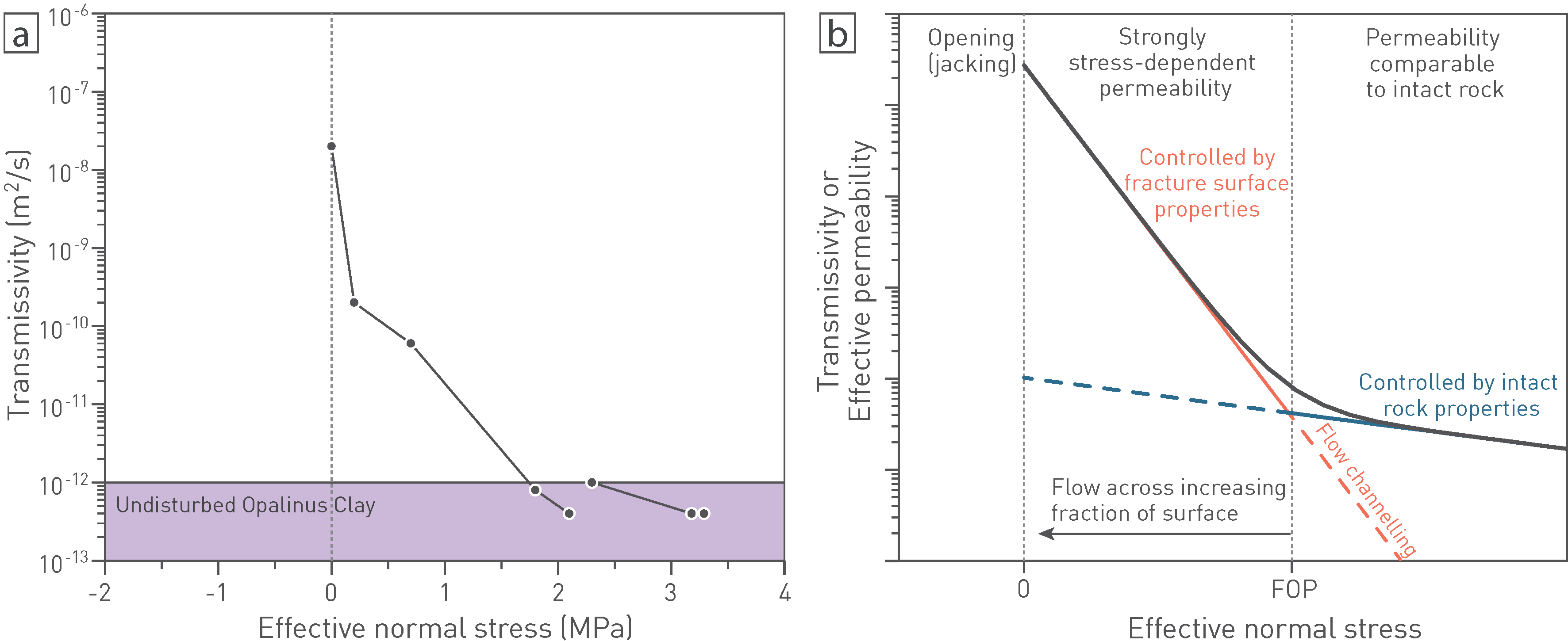
Fig. 5‑47:Dependence of fracture transmissivity on the effective normal stress
(a) Example of the GS experiment at Mont Terri (Marschall et al. 2017). (b) Conceptual understanding of flow regimes (modified after Donzé et al. 2023).
Conceptually, the FOP separates an effective permeability field at high effective stress, which is only marginally dependent on stress, from a field at low effective stress, which is strongly dependent on effective stress (Fig. 5‑47b). As the FOP is approached from initially higher effective stress, local dilatancy can occur, subsequently connecting dilatant parts of the fault and channelling fluid flow. Once fluid pressure achieves the critical value (FOP), transmissivities can increase by several orders of magnitude, as the effective confinement on the fault is gradually removed. It is important to note that the FOP is considered as a conceptual transition point, but absolute transmissivities may remain low (e.g. T < 10-10 m2/s at 0.5 – 1 MPa) before effective opening at close to zero effective stress (Fig. 5‑47a).
This conceptual understanding was recently confirmed in dedicated hydraulic tests in the Opalinus Clay in the RHE1 borehole at approximately 580 m depth below ground (Dossier VII, RHE1, Nagra (ed.) 2023b) (Fig. 5‑48). The test suite consisted of stepped-constant differential head injection tests (HI), followed by a withdrawal test applying constant differential head (HW) in an interval consisting of several fault planes with typical azimuth of 130° and main dips of 30 to 60° (Dossier V, RHE1, Nagra (ed.) 2023b).
Even after raising pore fluid pressure by more than 3 MPa in the test interval, no significant change in the flow rate was observed (point HI303 in Fig. 5‑48a). The stress field at the depth interval can be estimated from 3D geomechanical numerical modelling (Section 4.3 and Nagra 2024o). This is depicted by Mohr circles as initial condition in Fig. 5‑48b, where different circles represent the uncertainty in the total stresses (pore fluid pressure in the formation is assumed to be hydrostatic), and the dark grey circle as the average. The minimum value of the “failure” envelope of the fault planes can be estimated from post-peak strength of triaxial tests (Fig. 5‑27b). As illustrated in Fig. 5‑48b, the corresponding average Mohr circle prior to raising the fluid pressure is at safe distance from the failure envelope.
After increasing the pore fluid pressure to more than 5 MPa in the test interval (point HI306), the Mohr circle approximately intersects with the failure envelope, especially considering the uncertainties in the stress field. This is associated with a flow rate increase by 1 – 2 orders of magnitude. Furthermore, the effective normal pressure of the fault planes with dips of 30 to 60 degrees (indicated by dashed lines on the Mohr circle) at this stage was approximately 2 MPa, in good general agreement with a FOP as constrained in Mont Terri.
Fault opening is indicated with a progressive interval pressure drop after the HI306 phase, despite increasing the flow rate by nearly one order of magnitude. This was then followed by a pressure recovery after a constant head withdrawal test (HWS), where the pressure equilibrated to approximately 1 MPa above hydrostatic. The subsequent HW phase again allowed measurement of the flow rate, demonstrating major reduction to close to pre-stimulation values. The high transmissivities observed in the in-situ experiments (RHE1 and underground laboratories) followed by rapid reduction when injection is stopped is consistent with rapid pore fluid pressure equilibration across the fracture plane (Section 5.7.3). Over longer periods of time (months to years), “swelling” will dominate the self-sealing process and further reduce fracture transmissivity (Section 5.7.3).
Assuming a typical effective stress gradient of 0.01 – 0.015 MPa/m, a very similar range of effective stress (2 – 3 MPa) is reached for a FOP threshold at approximately 200 m overburden thickness. This is consistent with packer test results (Fig. 5‑41) and observations of water ingress and damp spots in tunnels (Gautschi 2017; Section 5.6.4).
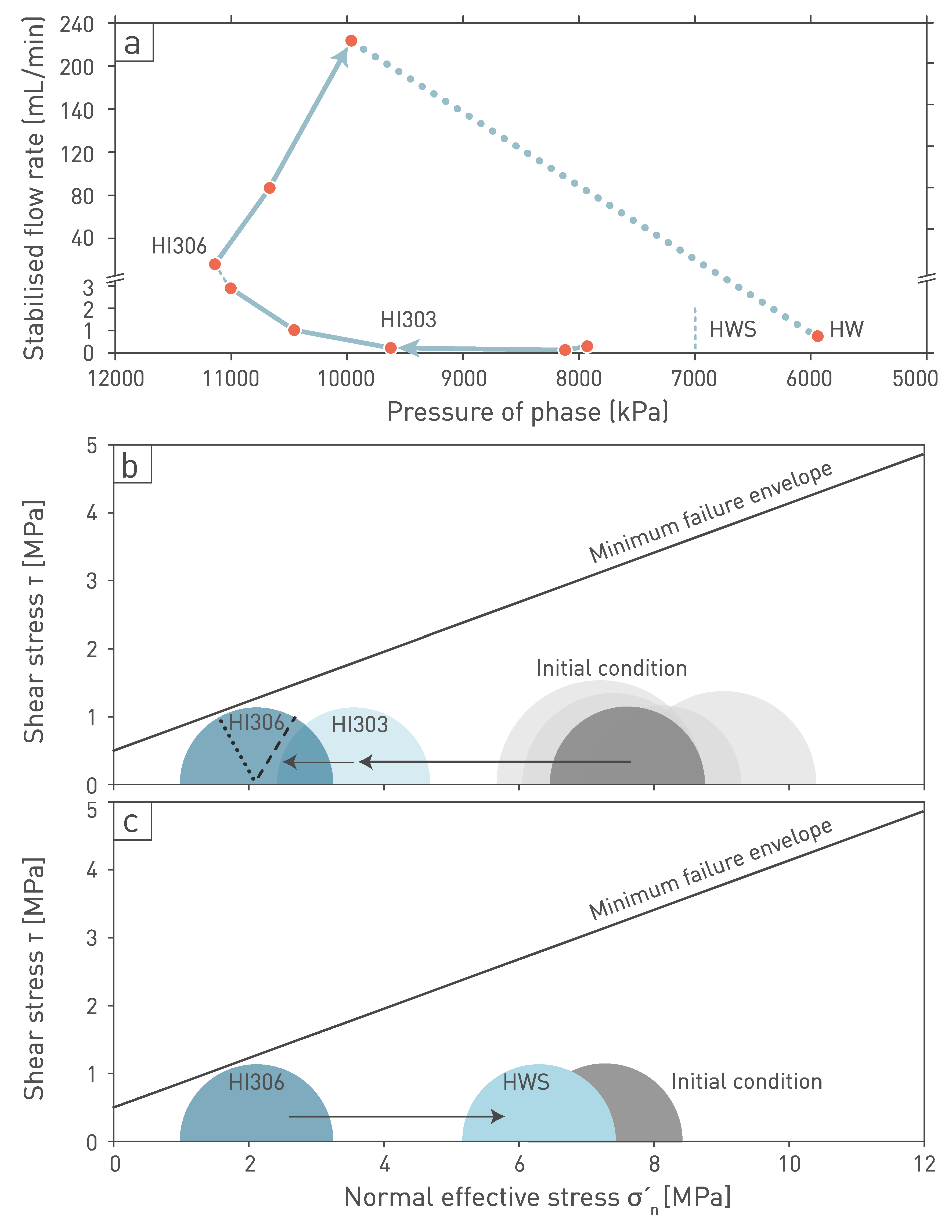
Fig. 5‑48:Relationship of fault-related flow and effective stress in the Opalinus Clay at the RHE1 borehole at approximately 580 m depth below ground
(a) Flow rate as a function of interval pressure (Nagra (ed.) 2023b, Dossier VII, RHE1). (b) and (c) show changes to the effective stresses and relationship to the Opalinus Clay minimum failure envelope as constrained from triaxial testing (Section 5.5.3). Mohr circles show stress field according to stress modelling results (Nagra 2024o). Dashed lines in figure (b) depict positions of fault dips between 30 and 60º on the Mohr circles. HI: constant head injection test, HW: withdrawal test (applying constant differential head), HWS: pressure recovery after constant head withdrawal test.